Method for manufacturing spar cap for wind turbine blade

A technology of wind turbine blades and spar caps, which is applied in the field of wind turbine manufacturing, can solve the problems of resin inability to flow, weak mechanical structure, and weak bonding, etc., and achieve the effect of improving the bonding strength

Inactive Publication Date: 2019-05-31
上伟(江苏)碳纤复合材料有限公司
View PDF3 Cites 2 Cited by
  • Summary
  • Abstract
  • Description
  • Claims
  • Application Information

AI Technical Summary

Problems solved by technology

[0002] Wind power blades are made from two halves to form a whole blade. The structural parts of traditional blades include: blade roots, spar caps, and webs. Traditional glass fiber prefabricated girders have slowed down due to the increase in blade size and lightweight requirements. Slow speed cannot meet the requirements of blade design. Nowadays, the use of carbon fiber pultruded sheets makes it possible to increase the size and weight of blades. Usually, pultruded sheets are laid in advance and stacked so that the sheets become the required length and thickness. Vacuum infusion makes the resin It can enter the gaps of the plates and between the layers of the plates. The pultruded plates are vertical in the stacked area, and the resin cannot flow. Therefore, a reliable infusion process and a reliable plate design are necessary.
[0003] At this stage, the manufacturer’s solution is to process the two sides of the board into bevels in the width direction of the board, so that the resin can fully flow, so as to achieve the purpose of full infiltration. Although the bevel design solves the perfusion problem, there is a certain space for the resin to be rich Set area, the mechanical structure of this area is relatively fragile, resulting in weak bonding

Method used


Image

  • Method for manufacturing spar cap for wind turbine blade
  • Method for manufacturing spar cap for wind turbine blade
  • Method for manufacturing spar cap for wind turbine blade

Examples


Embodiment Construction

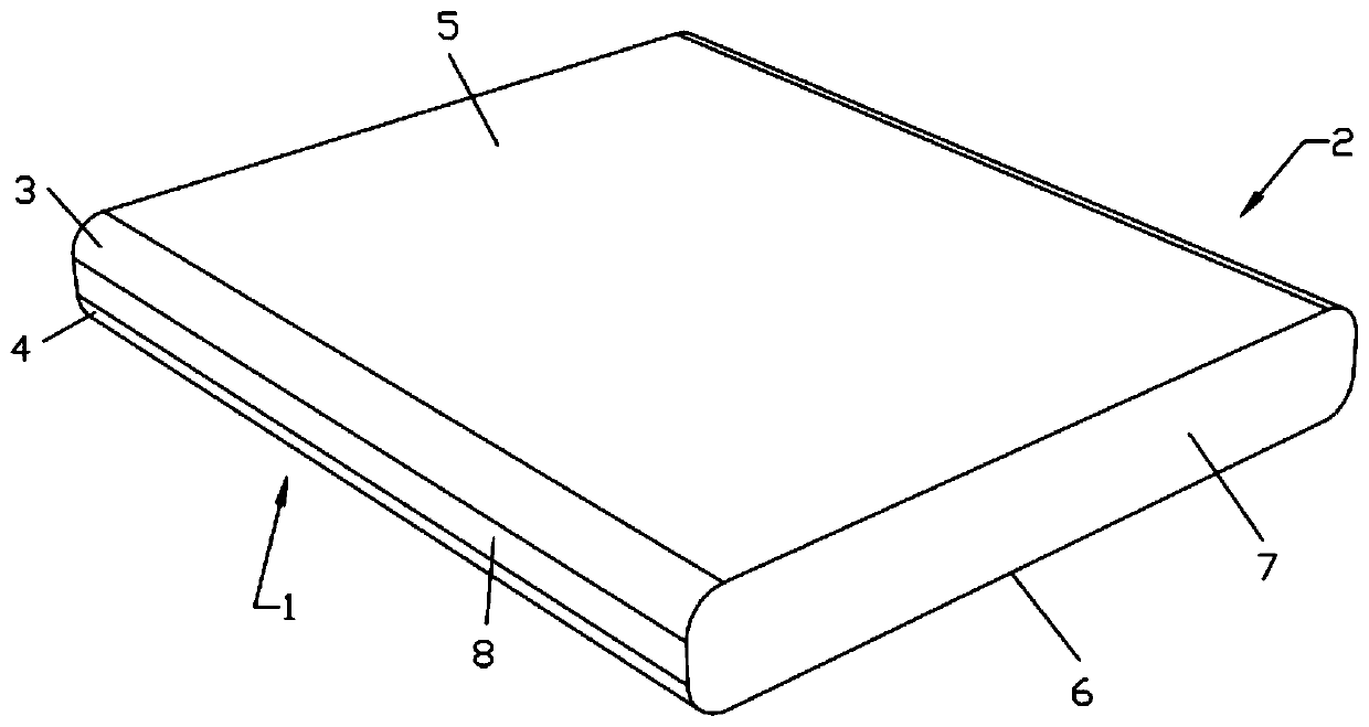
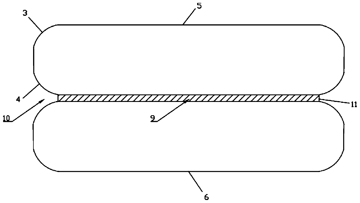
[0023] Such as Figure 1-2 Shown, be a kind of method of manufacturing the spar cap that is used for wind turbine blade of the present invention, comprise the steps:

[0024] S1. Provide a plurality of pultruded fiber sheets, each fiber sheet has a first side 1 and a second side 2 that are opposite to each other and extend longitudinally, and the first side 1 and the second side 2 respectively include The first arc-shaped surface 3 and the second arc-shaped surface 4, a first abutment surface 5 is provided between the first arc-shaped surface 3 of the first side part 1 and the first arc-shaped surface 3 of the second side part 2, A second abutment surface 6 is provided between the second arcuate surface 4 of the first side portion 1 and the second arcuate surface 4 of the second side portion 2 , between the first abutment surface 5 and the second abutment surface 6 The distance between them defines the thickness of the fiberboard; the two ends of the first abutment surface 5 ...


PUM


Abstract

The invention discloses a method for manufacturing a beam cap for a wind turbine blade, and relates to the technical field of wind turbine manufacturing. The method comprises the following steps thata plurality of fiber plates are provided, each fiber plate is provided with a first side part and a second side part which are arranged opposite to each other and extend in the longitudinal direction,the first side part comprise a first arc-shaped surface and a second arc-shaped surface, and the second side part comprise another first arc-shaped surface and another second arc-shaped surface; theplurality of fiber plates are stacked in a mold in the vertical direction; the outer surface of the stacked fiber plates is coated with a layer of vacuum film, and after coating is finished, vacuum areas are formed among the fiber plates; a vacuum pump is used for vacuumizing; resin is supplied; and all the fiber plates are combined together by curing the resin. According to the method for manufacturing the beam cap of the wind turbine blade, in the width direction of the plate, the two sides are processed into round corners, so that the resin cannot be gathered and can sufficiently flow, so that the purpose of full infiltration is achieved, and the bonding strength among the plates is improved.

Description

technical field [0001] The invention relates to the technical field of wind turbine manufacturing, in particular to a method for manufacturing a spar cap for a wind turbine blade. Background technique [0002] Wind power blades are made from two halves to form a whole blade. The structural parts of traditional blades include: blade roots, spar caps, and webs. Traditional fiberglass prefabricated girders have slowed down due to the increase in blade size and lightweight requirements. Slowness cannot meet the requirements of blade design. Nowadays, the use of carbon fiber pultruded sheets makes it possible to increase the size and weight of blades. Usually, pultruded sheets are pre-laid and stacked to make the sheets the required length and thickness. Vacuum infusion makes the resin It can enter the gaps of the plates and between the layers of the plates. The pultruded plates are vertical in the stacked area, and the resin cannot flow. Therefore, a reliable infusion process an...

Claims


Application Information

Patent Timeline
Patent Type & Authority Applications(China)
IPC IPC(8): B29C70/36B29L31/08
Inventor 张晨张舒
Owner 上伟(江苏)碳纤复合材料有限公司
Why Eureka
Try Eureka