Improved structure of peanut combine harvester

A combine harvester and harvester technology, applied to the improved structure of auger parts and conveying troughs, and in the field of picking and harvesting, it can solve problems such as difficult disassembly and assembly, machine operation stoppage, poor conveying, etc., to avoid complicated manufacturing process, Improved working speed and simple structure

Pending Publication Date: 2019-06-04
NANJING AGRI MECHANIZATION INST MIN OF AGRI
View PDF0 Cites 0 Cited by
  • Summary
  • Abstract
  • Description
  • Claims
  • Application Information

AI Technical Summary

Problems solved by technology

[0008] The outstanding problem at present is that the rotation direction of the pick-up teeth and the auger are directly connected by the chain and the sprocket, which will form a counter-rotation, which is not suitable for the actual operation requirements of the machine tool. Complicated, heavy, and faulty defects
[0009] Secondly, the problem of the connection between the conveying trough and the auger, due to their relatively large volume, they often need to be disassembled and connected to each other during transportation, operation, maintenance and other links. In the past, they were connected by bolts and screws, which made disassembly and assembly very difficult. The connection position is relatively concentrated in force and easily damaged
[0010] In addition, the transmission shaft of the conveying trough is easy to be entangled with peanut seedlings, which causes the transmission chain of the conveying trough to easily skip teeth, and the conveying scraper is distorted and deformed, resulting in poor conveying and affecting the quality of work. , affecting the operation speed, quality and efficiency

Method used


Image

  • Improved structure of peanut combine harvester
  • Improved structure of peanut combine harvester
  • Improved structure of peanut combine harvester

Examples


Embodiment Construction

[0051] The structure of the present invention will be further described in detail below in conjunction with the accompanying drawings.

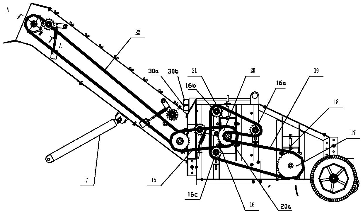
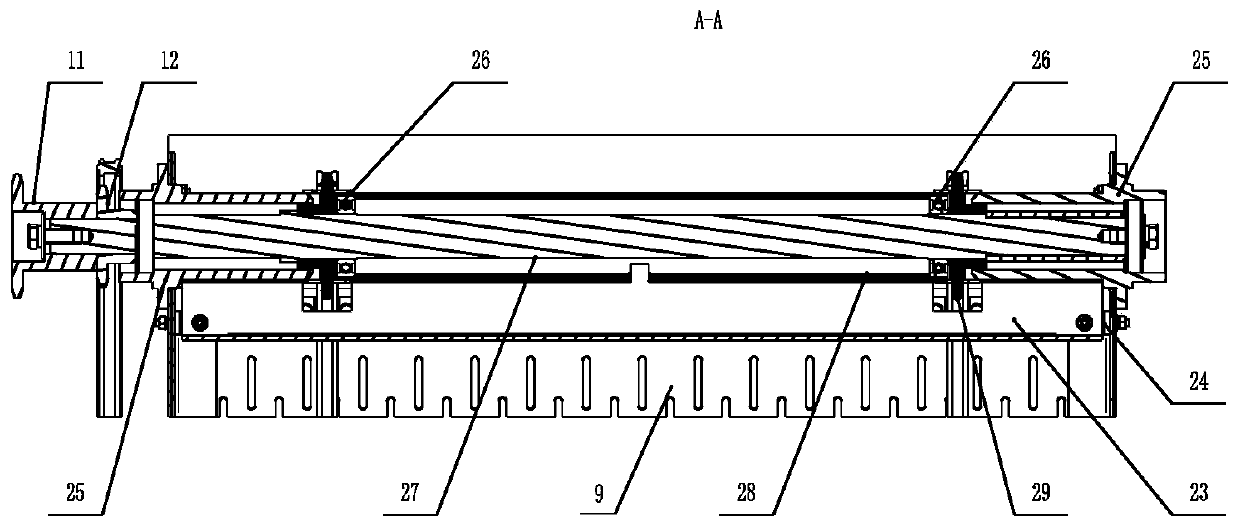
[0052] An improved structure of a peanut combine harvester. From the front of the harvester to the rear, there are semicircular seedling pressing rods 1 with openings upwards, protruding seedling sliding plates 3 and picking spring teeth 2 that rotate vertically, and then horizontally. The auger 5, the rear outlet of the auger 5 is connected to the conveying trough inclined upwards at the tail,

[0053] The tail part is obliquely upwards to form a flat rectangular conveying trough, and the front and rear parts are equipped with transmission shafts 27 horizontally and horizontally passing through the conveying trough shell. For the conveying trough sprocket 29, two pairs of conveying trough sprockets 29 are configured with two circulating conveying trough transmission chains 10, and a large number of horizontal scraper strips 8 are fixed on th...


PUM


Abstract

The invention relates to an improved structure of a peanut combine harvester. The improved structure is characterized in that three tensioning wheels are arranged at corresponding appointed positionsaround a pickup sprocket and an auger shaft end sprocket, and opposite-direction rotation of an auger (5) and pickup elastic teeth (2) is achieved by the appointed rotation direction of a chain; a transverse square-tube-shaped lower support crossbeam (30a) and a transverse square-tube-shaped upper support crossbeam (30b) which are vertically staggered are respectively fixed to the upper edge of the inlet of a conveying chute and the upper edge of the outlet of an auger shell, the two crossbeams are stacked during combination, two upwardly vertical insertion rods (30c) are fast hooked, fast demounting of the harvester during transfer is facilitated, and convenient and reliable connection is achieved; the rotation of a tubular anti-winding pipe (28) arranged on a transmission shaft (27) at the rear of the conveying chute is limited by an anti-winding limit plate (23), and the peanut seedling clamping and winding problem is solved by the anti-winding pipe (28) and a chute connecting sleeve (24) fixed to a chute shell wall. By the improved structure, operation speed, quality and efficiency are improved greatly.

Description

technical field [0001] The invention relates to an improved structure of parts of an agricultural machinery peanut combine harvester, in particular to an improved structure of picking and harvesting, auger parts and conveying troughs of a peanut harvester Background technique [0002] As an important oil crop and high-quality protein resource, peanut is in the forefront of the world in terms of planting area and output in my country. According to the China Statistical Yearbook, in 2015, my country's peanut planting area was 69.236 million mu, with an output of 16.44 million tons, ranking second and first in the world respectively. Among the developed countries, only a few countries such as the United States carry out large-scale planting. In 2016, the planting area was 626khm2, accounting for 2.46% of the world's peanut planting area. In my country, peanut planting is widely distributed, mainly concentrated in Henan, Shandong, Guangdong, Hebei, Liaoning, Anhui, Jiangsu and ...

Claims


Application Information

Patent Timeline
Patent Type & Authority Applications(China)
IPC IPC(8): A01D29/00A01D33/00A01D89/00
Inventor 王申莹胡志超曹明珠于昭洋徐弘博高学梅
Owner NANJING AGRI MECHANIZATION INST MIN OF AGRI
Why Eureka
Try Eureka