
Eureka
For R&D, Eureka makes reading and utilizing patents & technical documents easy.
Eureka AIR
Designed for self-driven R&D workflows. Generate viable solutions, solve complex R&D challenges, empower your innovation with AI.

Eureka Materials
Designed for material experts only. Revolutionize your material R&D, from search, analyze, to developing new materials.

TechResearch
Generate reliable direction feasibility study reports for your R&D in just a few steps.

TechSeek
Discover and master advanced knowledge NOW. Basics, ideas, possibilities, all at once.

TechMind
As an expert in R&D Theories, TechMind can generates customized viable solutions instantly.

TechRisk
Analyze your overall solution with one click, know your potential R&D risks in advance.

TechMonitor
Get weekly tech updates, stay abreast of the latest tech innovations and key insights.
Multi-head sauce filling machine
A multi-head sauce and material filling technology, applied in packaging, liquid materials, bottle filling, etc., can solve the problems of long time for specification adjustment, increased rework time, and many filling heads, so as to reduce waste time and ensure efficiency and quality , the effect of breaking through the speed bottleneck
- Summary
- Abstract
- Description
- Claims
- Application Information
AI Technical Summary
Problems solved by technology
Method used
Image

Examples
Embodiment 1
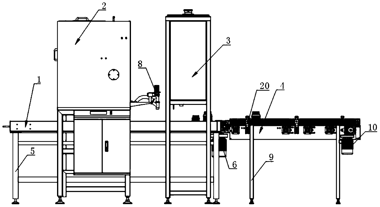
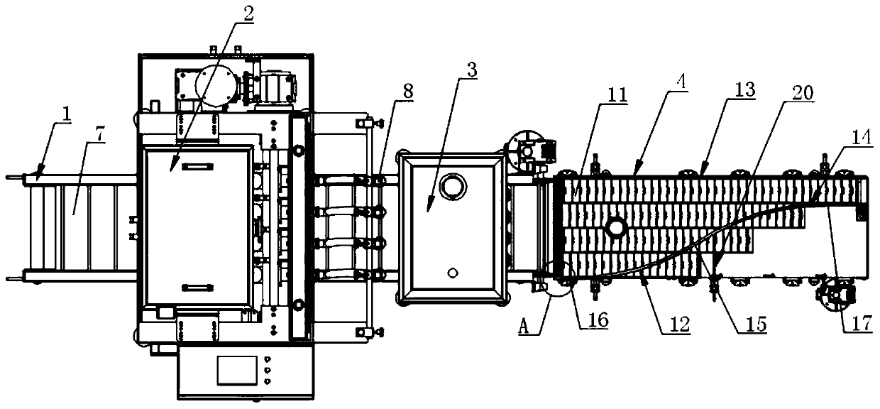
[0029] Such as figure 1 and figure 2 As shown, a multi-head sauce filling machine includes a stepping conveying device 1, a first filling device 2, a second filling device 3 and a collection conveying device 4, and the stepping conveying device 1 is arranged on the first Below the first filling device 2 and the second filling device 3, the first filling device 2 and the second filling device 3 are arranged in sequence along the running direction of the stepping conveying device 1, and the collecting and conveying device 4 is arranged at The tail end of the stepping conveying device 1 , and the running direction of the collecting and conveying device 4 is consistent with the running direction of the stepping conveying device 1 .
[0030] Described step conveying device 1 comprises first frame 5, first drive motor 6 and first conveyor belt 7, and described first conveyor belt 7 is installed on described first frame 5 top, and described first drive motor 6 is fixed on the firs...
Embodiment 2
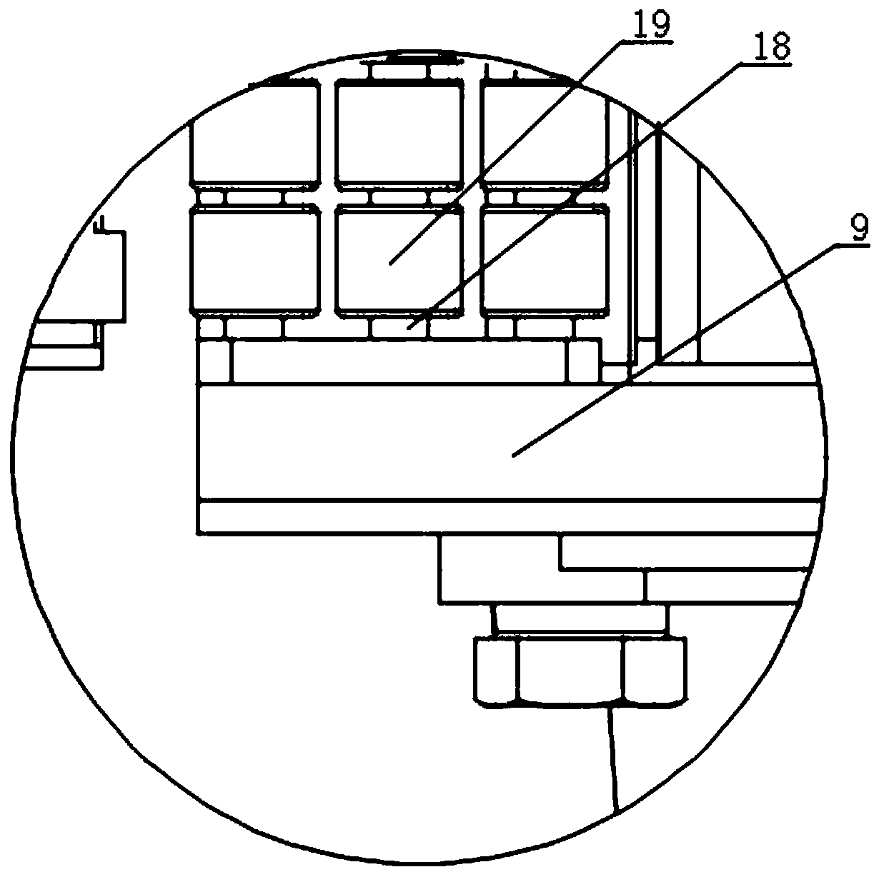
[0038] Such as figure 2 , Figure 4 and Figure 5 As shown, in this embodiment, on the basis of Embodiment 1, a plurality of stabilizers 20 are installed on both sides of the second frame 9, and the stabilizers 20 include a stabilizer bar 21, a connecting seat 22, a connecting sleeve 23 and The locking head 24, the connecting seat 22 is fixedly connected to the second frame 9, the connecting sleeve 23 is fixedly installed on the connecting seat 22, and the connecting sleeve 23 is radially oppositely arranged with Two first threaded holes, the top of the connecting sleeve 23 is provided with a second threaded hole in the axial direction, the stabilizing rod 21 is connected with the connecting sleeve 23 through the two first threaded holes, one end of the stabilizing rod 21 It is pressed against the outer surface of the guide device 12 . The stabilizer 20 is used to support the first guide plate 13 and the second guide plate 14 . The heads of stabilizing bars 21 of a plural...
PUM
 Abstract
Description
Claims
Application Information
 - R&D Engineer
- R&D Manager
- IP Professional
- Industry Leading Data Capabilities
- Powerful AI technology
- Patent DNA Extraction
Browse by: Latest US Patents, China's latest patents, Technical Efficacy Thesaurus, Application Domain, Technology Topic, Popular Technical Reports.
© 2024 PatSnap. All rights reserved.Legal|Privacy policy|Modern Slavery Act Transparency Statement|Sitemap|About US| Contact US: help@patsnap.com