
Coordinate algorithm of MARK points on printed board in high-precision printing machine based on machine vision

A machine vision, high-precision technology, applied in printing, instruments, computing, etc., can solve the problems of insufficient light and lighting environment, low accuracy of positioning process, waste of time, etc., to improve the efficiency of equipment adjustment, reduce requirements, and improve convenience sexual effect

Inactive Publication Date: 2019-06-07
XI'AN INST OF OPTICS & FINE MECHANICS - CHINESE ACAD OF SCI
View PDF0 Cites 0 Cited by
  • Summary
  • Abstract
  • Description
  • Claims
  • Application Information

AI Technical Summary

Problems solved by technology

[0002] In the SMT industry, circuit boards are coated with solder paste by a printing machine, and then undergo component assembly and reflow soldering processes, and finally realize the complete production of PCBs; the printing machine in the prior art has been converted from manual coating to semi-automatic printing. , the cylinder drives the scraper and the stencil to drop to the surface of the PCB. After the scraper lands, the solder paste is repeatedly scraped left and right along the surface of the stencil; the reason why this process is semi-automatic is that it is necessary to manually fix the PCB on the fixture and remove it manually. process, which is a waste of time;
[0003] We are committed to making a fully automatic solder paste printing machine, and at the same time we need to improve the squeegee coating accuracy; in the design of a fully automatic printing machine, the alignment between the printing screen and the PCB is very important, and the current alignment is only through MARK Points for laser through test alignment, or manual alignment; due to insufficient light and lighting environment, these alignment methods have some disadvantages, cannot be reliable and accurate alignment; it is also not conducive to the realization of a fully automatic alignment process
In order to achieve fully automatic alignment, we have designed a visual alignment component, which is set up with an industrial camera as the core, and can automatically align, but the alignment process needs to be moved to adjust the interaction between the industrial camera and the MARK point, as well as the mesh board and the PCB board. Positional relationship; the existing technology does not have a MARK point positioning algorithm suitable for our automatic solder paste printing machine, and the current positioning technology based on laser technology and grating ruler positioning has low accuracy in the positioning process

Method used


Image

  • Coordinate algorithm of MARK points on printed board in high-precision printing machine based on machine vision
  • Coordinate algorithm of MARK points on printed board in high-precision printing machine based on machine vision

Examples


specific Embodiment approach

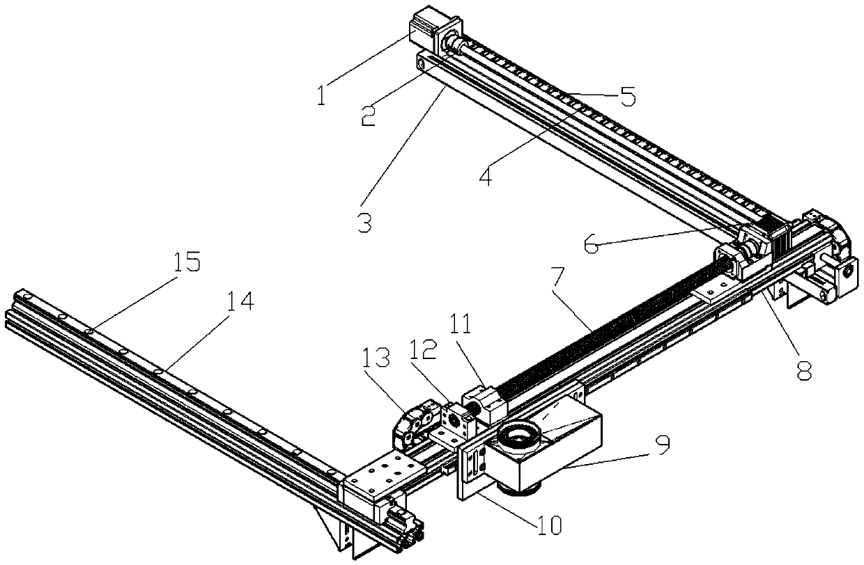
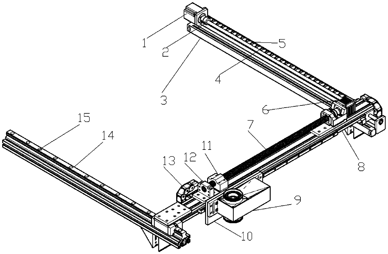
[0029] The coordinate algorithm of the MARK point on the printed board in the high-precision printing machine based on machine vision disclosed by the present invention, wherein:

[0030] The camera moves through a two-dimensional drive mechanism; above the camera is a printed stencil, and below the camera is a PCB board; the printed stencil and the PCB board respectively contain two MARK points (points A and B on the PCB board, and points A and B on the printed stencil) two points C and D); the number of MARK points on the printed stencil and the PCB board are the same, and the positions match; the two matching MARK points on the printed stencil and the PCB board form a group; the two-dimensional drive mechanism includes X moving components , Y moving component, X grating ruler and Y grating ruler; the two-dimensional drive mechanism includes two photoelectric switches located at the mechanical origin, namely the X photoelectric switch and the Y photoelectric switch; the mecha...


PUM


Abstract

The invention discloses a coordinate algorithm of MARK points on a printed board in a high-precision printing machine based on machine vision, which can reasonably, reliably and accurately realize thepositioning of MARK. The algorithm is reasonable and the technical scheme is efficient and reliable. The coordinate algorithm comprises the following steps: (1) primarily aligning a printed steel screen and the PCB, and moving each group of MARK points to align to partially coincide; (2) driving a camera by a two-dimensional driving mechanism and then moving the camera to the mechanical origin; (3) the coordinates of the mechanical origin measured by the camera being (H, L); (5) measuring a Mark point A on the PCB in the camera field of view to obtain the initial pixel coordinate (xp1, yp1) of the mark point and the mechanical coordinates (xj1, yj1) at this time, calculating to obtain the actual coordinates of the MARK point A being X=x1+D<xj1>-DH; X=y<p1>+D<yj1>-DL, in the sameprocess, measuring the actual coordinates of a MARK point B on the PCB in turn, and measuring the actual coordinates of MARK points C and D on the printed steel screen in turn; and (6) performing driving by the two-dimensional driving mechanism.

Description

technical field [0001] The invention relates to an alignment algorithm on a printing machine, which is specifically used for positioning the MARK points of a PCB board and a printing steel net in a solder paste printing machine. Background technique [0002] In the SMT industry, circuit boards are coated with solder paste by a printing machine, and then undergo component assembly and reflow soldering processes, and finally realize the complete production of PCBs; the printing machine in the prior art has been converted from manual coating to semi-automatic printing. , the cylinder drives the scraper and the stencil to drop to the surface of the PCB. After the scraper lands, the solder paste is repeatedly scraped left and right along the surface of the stencil; the reason why this process is semi-automatic is that it is necessary to manually fix the PCB on the fixture and remove it manually. process, which is a waste of time; [0003] We are committed to making a fully autom...

Claims


Application Information

Patent Timeline
IPC IPC(8): B41M1/12B41M1/26G06T7/70
Inventor 张国琦曹捷强鹏飞刘永安闫兴涛
Owner XI'AN INST OF OPTICS & FINE MECHANICS - CHINESE ACAD OF SCI
Learn More