Main conveying device, feeding device and numerical control edging machining center

A transmission device and feeding device technology, applied to metal processing equipment, grinding machines, conveyors, etc., can solve problems such as timing belt offset, plate offset, and processing errors, so as to reduce processing errors, avoid offsets, and improve production The effect of precision

Pending Publication Date: 2019-06-07
佛山市西菱欧科技有限公司
View PDF0 Cites 1 Cited by
  • Summary
  • Abstract
  • Description
  • Claims
  • Application Information

AI Technical Summary

Problems solved by technology

[0003] The purpose of the embodiment of the present invention is to provide a main conveying device, a feeding device and a numerical control edging processing center, so as to improve the plate conveying device of the existing edging processing equipment with a drum structure, which causes the synchronous belt to easily occur when grinding large plates. Offset, which in turn leads to the offset of the plate, resulting in the problem of processing errors

Method used


Image

  • Main conveying device, feeding device and numerical control edging machining center
  • Main conveying device, feeding device and numerical control edging machining center
  • Main conveying device, feeding device and numerical control edging machining center

Examples


Embodiment 1

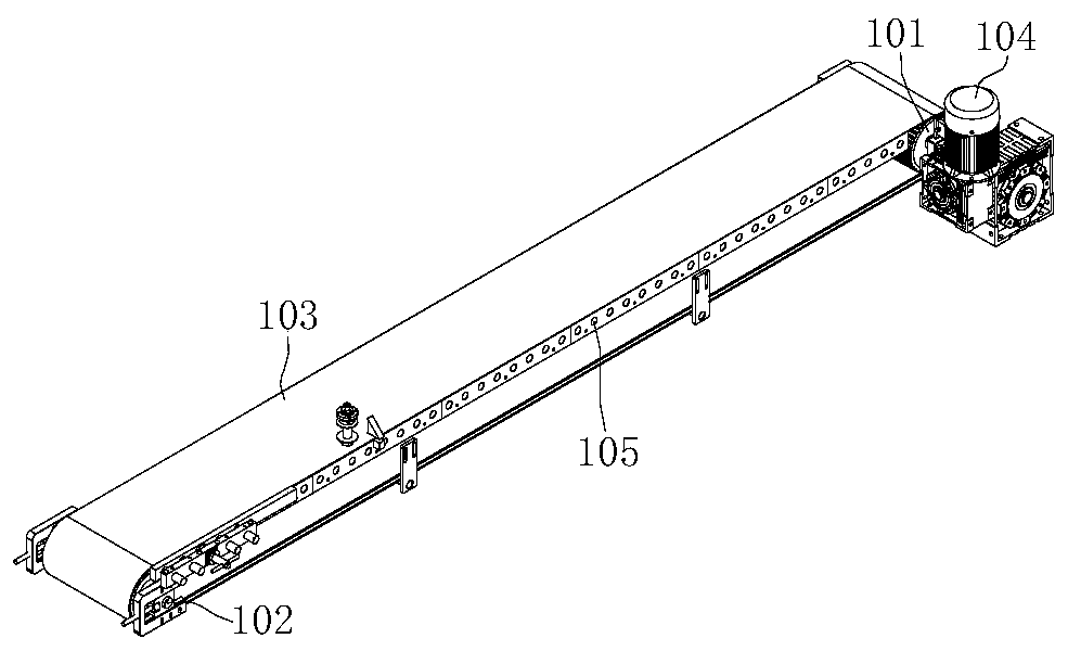
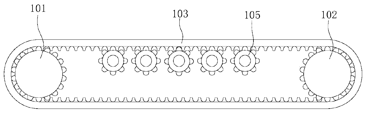
[0044] refer to figure 1 and figure 2 , the present embodiment provides a main transmission device 107, including a frame 106, a motor 104, a driving tooth 101, a driven tooth 102, a conveyor belt 103 and a plurality of rollers 105, a motor 104, a driving tooth 101 and a driven tooth 102 Both are installed on the frame 106, the motor 104 drives and connects the driving gear 101, the conveyor belt 103 is wound between the driving gear 101 and the driven gear 102, the conveyor belt 103 is respectively engaged with the driving gear 101 and the driven gear 102, and a plurality of rollers 105 All are installed on the frame 106, and a plurality of rollers 105 are arranged at intervals along the direction from the driving gear 101 to the driven gear 102, the rollers 105 are engaged with the conveyor belt 103, and the plurality of rollers 105 are all located inside the conveyor belt 103.

[0045] The main transmission device 107 provided in this embodiment utilizes the engagement be...


PUM


Abstract

The invention provides a main conveying device, a feeding device and a numerical control edging machining center, and belongs to the field of machining centers. The main conveying device comprises a rack, a motor, a driving gear, a driven gear, a conveying belt and a plurality of rollers, wherein the motor, the driving gear and the driven gear are installed on the rack, the motor is in driving connection with the driving gear, the conveying belt is wound between the driving gear and the driven gear and engaged with the driving gear and the driven gear, the multiple rollers are installed on therack and arranged at intervals in the direction from the driving gear towards the driven gear, the rollers are engaged with the conveying belt, and the rollers are located on the inner side of the conveying belt. The main conveying device makes use of the engagement among the driving gear, the driven gear and the conveying belt to form stable conveying, the rollers can form a support to the conveying belt, the plates of various sizes and shapes can be better conveyed so that the plates can move along the straight line and can be avoided from lateral deviation, and the straightness of the processed plates is guaranteed.

Description

technical field [0001] The invention relates to the field of machining centers, in particular to a main transmission device, a feeding device and a numerically controlled edging machining center. Background technique [0002] Now, with non-metallic brittle plates such as various stone materials and artificial stone materials, ceramics, and glass, they are used more and more in public buildings and residential decoration. In order to increase the aesthetic feeling, it is necessary to process the edges of these plates in various shapes, such as grinding straight edges, beveled round edges, duck mouth edges, etc. At present, in order to save labor and reduce labor intensity, the edge grinding of the above-mentioned plates is basically done by machines. However, due to the different materials of the above-mentioned various plates, plus various shapes and different processing sizes, the existing edging processing equipment, because its plate conveying device adopts a flat-bottom...

Claims


Application Information

Patent Timeline
Patent Type & Authority Applications(China)
IPC IPC(8): B65G23/06B65G13/00B24B21/18
Inventor 陈益鸿王周
Owner 佛山市西菱欧科技有限公司
Why Eureka
Try Eureka