Compound subsurface flow constructed wetland with high drop difference and adjustable water outflow

A technology of artificial wetland and high drop, applied in biological water/sewage treatment, water/sludge/sewage treatment, chemical instruments and methods, etc., can solve problems such as complex water flow direction, large head loss, and easy blockage, etc., to achieve The overall anti-clogging performance is good, the effect of promoting plant growth and uniform water distribution

Pending Publication Date: 2019-06-07
WUHAN ZHONGKE HYDROBOLOGY ENVIRONMENTAL ENG
View PDF0 Cites 2 Cited by
  • Summary
  • Abstract
  • Description
  • Claims
  • Application Information

AI Technical Summary

Problems solved by technology

[0003] Due to the complex direction of water flow in traditional composite subsurface flow constructed wetlands, and compared with conventional subsurface flow wetlands, the water flow in the filler needs to pass through a longer or deeper filler layer, resulting in large water resistance and large head loss, and is more prone to clogging than conventional wetlands. It is often necessary to add a backwash device in the packing layer
Adding backwashing devices in the packing layer will increase the cost of construction, operation and maintenance, and increase the difficulty and complexity of post-management

Method used


Image

  • Compound subsurface flow constructed wetland with high drop difference and adjustable water outflow
  • Compound subsurface flow constructed wetland with high drop difference and adjustable water outflow
  • Compound subsurface flow constructed wetland with high drop difference and adjustable water outflow

Examples


Embodiment 1

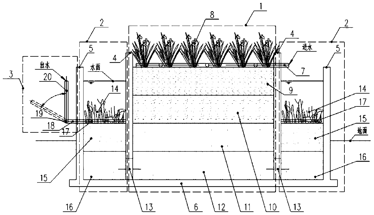
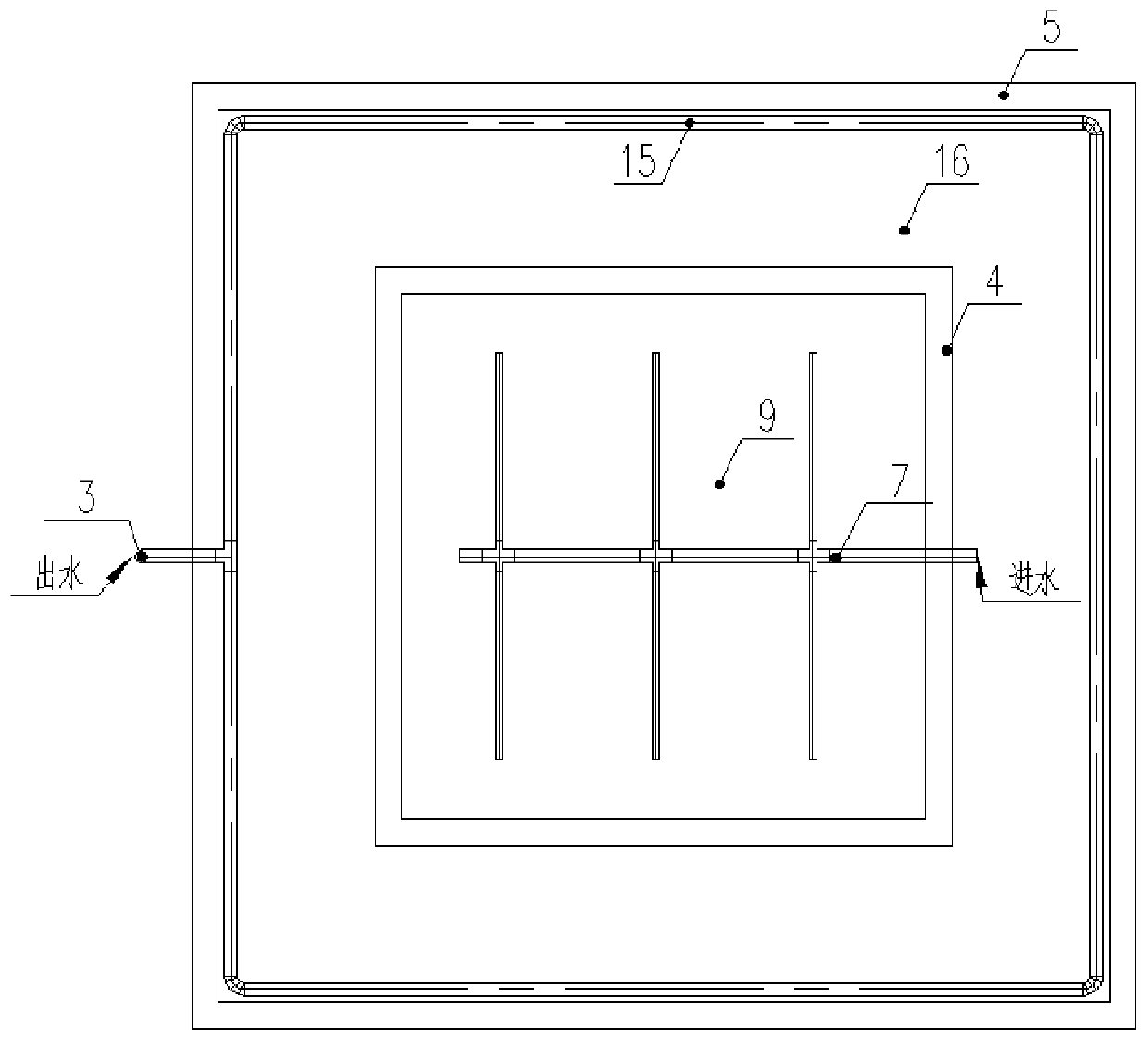
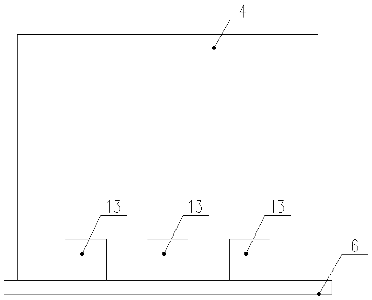
[0032] Such as Figure 1~3 As shown in the figure, a composite subsurface flow artificial wetland with high drop and adjustable discharge water includes a downward wet area 1, and an upward wet area 2 is circularly arranged around the downward wet area 1, and the bottom of the downward wet area 1 is evenly arranged with a 2 A water hole 13 connected at the bottom, a water distribution pipe 7 is installed on the top of the downward wet area 1, and the vegetation layer 14 of the upward pool, the filling layer 15 of the first upward pool and the second upward pool are sequentially arranged in the upward wet area 2 from top to bottom Filling layer 16, the top of the filling layer 15 of the first upward pool is provided with a water collection pipe 17, the water collection pipe 17 is connected to one end of the water outlet horizontal pipe 18, and the other end of the water outlet horizontal pipe 18 passes through the upward wet area 2 and then passes through the swivel elbow 19 and...

Embodiment 2

[0052] The specifications of the descending wet area 1 are: length × width = 5m × 5m.

[0053] The vegetation layer 8 of the descending pond is canna, and the planting density is 9 plants / ㎡.

[0054] The first descending pool filler layer 9 is gravel filler with a particle size of 8-10mm, and the thickness is 350mm.

[0055] The second down tank filler layer 10 is crushed stone filler with a particle size of 12-15 mm, and a thickness of 350 mm.

[0056] The third down tank filler layer 11 is gravel filler with a particle size of 20-30 mm, and a thickness of 350 mm.

[0057] The fourth down tank filler layer 12 is gravel filler with a particle size of 50-70 mm, and a thickness of 350 mm.

[0058] The water distribution pipe 7 is a PE perforated pipe of DN80, the diameter of the water outlet hole is 8mm, and the hole distance between adjacent water outlet holes is 150mm.

[0059] Partition wall 4 is a reinforced concrete partition wall with a height of 1.6m. The width and he...


PUM

PropertyMeasurementUnit
Particle sizeaaaaaaaaaa

Abstract

The invention discloses a compound subsurface flow constructed wetland with the high drop difference and the adjustable water outflow. The constructed wetland comprises a downward wetland area, wherein an upward wetland area is circularly arranged around the downward wetland area, the bottom circumference of the downward wetland area is evenly provided with water passing holes communicating with the bottom of the upward wetland area, the top of the downward wetland area is provided with a water distribution pipe, the interior of the upward wetland area is successively provided with an upward pool vegetation layer, a first upward pool filler layer and a second upward pool filler layer from top to bottom, the top of the first upward pool filler layer is provided with a water collection pipe,the water collection pipe communicates with one end of each water outlet transverse pipe, and the other end of each water outlet transverse pipe, after passing through the upward wetland area, communicates with the bottom end of each water outlet vertical pipe through each movable elbow. The water outlet height can be freely adjusted by the movable elbows, so that no-void of the filler layer of the downward wetland area top layer can be ensured during the normal operation of the wetland, and the void can be controlled when the filler layer of the top of the downward wetland area is blocked.

Description

technical field [0001] The invention relates to the technical field of sewage treatment by composite subsurface flow constructed wetlands, in particular to a composite subsurface flow constructed wetland with high drop and adjustable water discharge. Background technique [0002] Composite subsurface flow constructed wetland is a composite superposition of traditional horizontal subsurface flow constructed wetland or vertical subsurface flow constructed wetland unit in the horizontal or vertical direction, and improves the uniformity of water distribution and the living environment of microorganisms in the subsurface flow wetland filler layer by changing the single flow direction. Improving the purification efficiency is currently a hot spot in the research of subsurface flow constructed wetlands. [0003] Due to the complex direction of water flow in traditional composite subsurface flow artificial wetlands, and compared with conventional subsurface flow wetlands, the water...

Claims


Application Information

Patent Timeline
IPC IPC(8): C02F3/32
Inventor 刘志军汪尚朋徐小乐徐恒陈军
Owner WUHAN ZHONGKE HYDROBOLOGY ENVIRONMENTAL ENG
Why Eureka
Try Eureka