Folding table top structure of sewing machine

A table structure and sewing machine technology, which is applied in the field of sewing machines, can solve the problems of not being able to fully meet the needs of the tabletop extension and poor adjustability, and achieve the effects of convenient packaging and transportation, reduced area, and minimized size

Pending Publication Date: 2019-06-07
BULLMER ELECTROMECHANICAL TECH
View PDF4 Cites 0 Cited by
  • Summary
  • Abstract
  • Description
  • Claims
  • Application Information

AI Technical Summary

Problems solved by technology

[0004] The workbench in the above-mentioned patent documents has a foldable front plate, which can adjust the volume of the workbench to a certain extent, but the front plate can only be hinged and rotated, which has poor adjustability and cannot fully meet the extension requirements of the workbench

Method used


Image

  • Folding table top structure of sewing machine
  • Folding table top structure of sewing machine
  • Folding table top structure of sewing machine

Examples


Embodiment 1

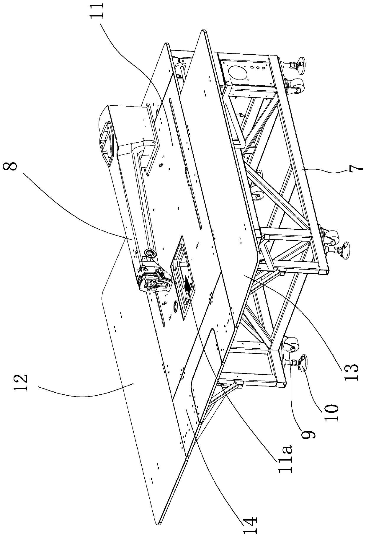
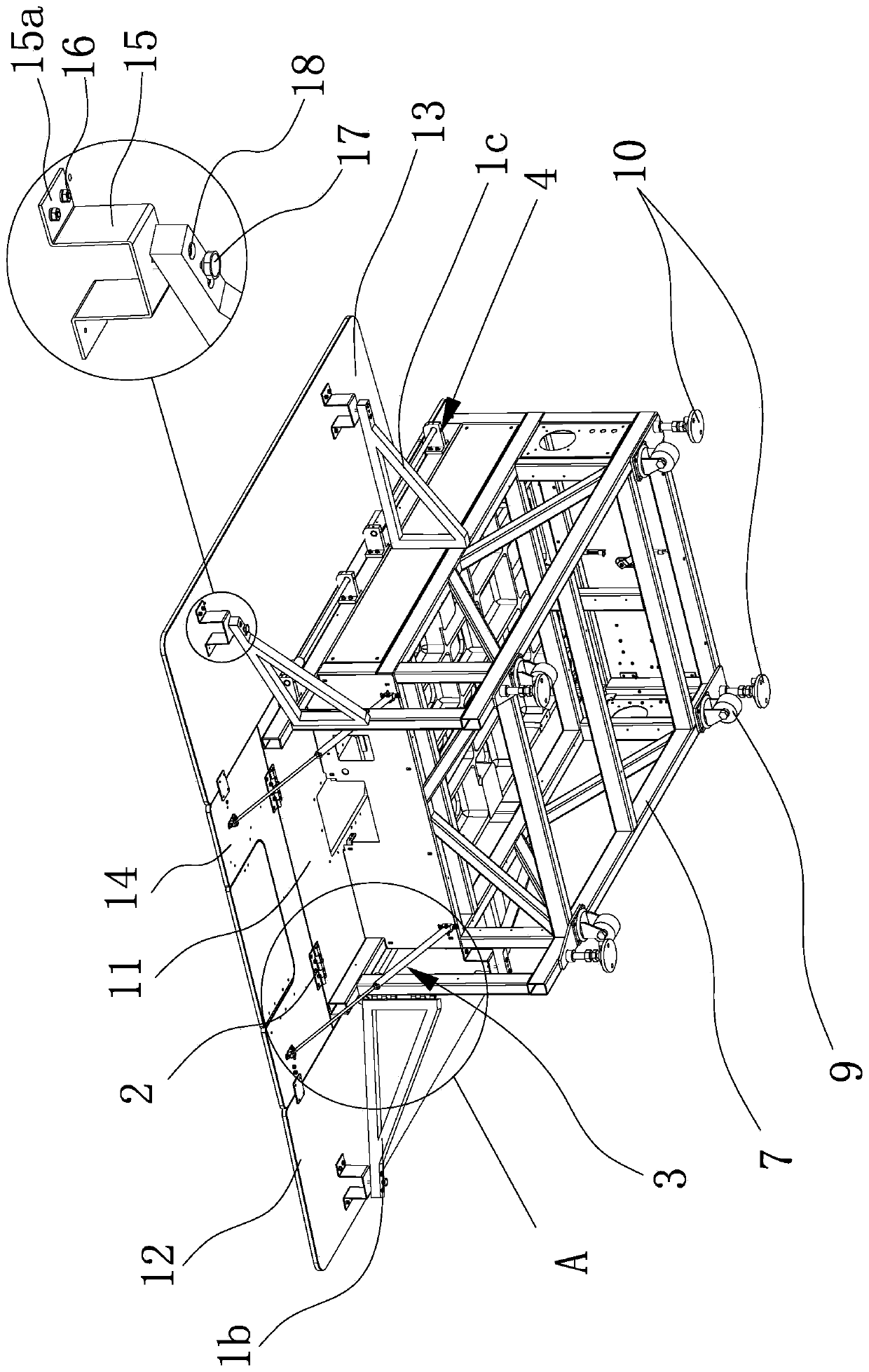
[0040] Such as Figure 1 to Figure 3 As shown, the sewing machine in this embodiment includes a frame 7 on which a machine head 8 is fixed, and the bottom of the frame 7 is provided with rollers 9 and support feet 10 capable of lifting. The folding table structure includes a rectangular main table Plate 11, the main plate 11 is provided with a through hole 11a facing the head of the machine head 8, the main plate 11 is fixed on the upper end of the frame 7, and one end of the main plate 11 is connected with a front auxiliary plate through a hinge 12. Platen 14, left auxiliary platen 12 and right auxiliary platen 13 are respectively provided on both sides of main platen 11, between left auxiliary platen 12 and main platen 11, between right auxiliary platen 13 and main platen 11 Both of them are connected through the connecting assembly 4 that can make the left auxiliary table 12 and the right auxiliary table 13 swing and fold, and the left auxiliary table 12 and the right auxil...

Embodiment 2

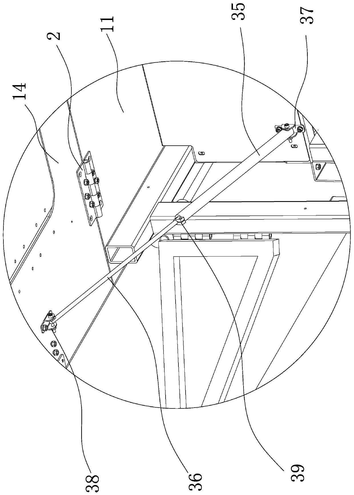
[0047] Such as Figure 4 with Figure 5 As shown, the present embodiment is substantially the same as the first embodiment, the difference is that the support assembly 3 in the present embodiment includes a support rod 31, a support rod 2 32, a fixed seat 33 fixedly connected with the frame 7 and a The fixed seat 2 34 that the bottom of the front auxiliary plate 14 is fixed; one side of the support rod 31 has a groove 31a, and one end of the support rod 31 is hinged with one side of the support rod 2 32 and the support rod 2 32 is embedded Into the groove 31a, the other end of the support rod one 31 is hinged to the second fixing seat 34, and the other end of the support rod two 32 is hinged to the first fixing seat 33.


PUM


Abstract

The invention provides a folding table top structure of a sewing machine and belongs to the technical field of sewing machines. The technical problem is solved that a table top structure on an existing sewing machine is inconvenient to transport. The sewing machine comprises a rack, the folding table top structure comprises a rectangular main table board, and the main table board is fixedly arranged at the upper end of the rack; a front auxiliary table board is connected to one end of the main table board through a hinge, a left auxiliary table board and a right auxiliary table board are arranged at the two sides of the main table board respectively, the left auxiliary table board and the main table board as well as the right auxiliary table board and the main table board are connected through connection assemblies capable of making the left auxiliary table board and right auxiliary table board swing and folded, and the left auxiliary table board and the right auxiliary table board canalso move on the connection assemblies in the length direction of the main table board; a left supporting rack and a right supporting rack which extend outwards and can swing are connected to the twosides of the rack respectively. The auxiliary table tops of the folding table top structure can be turned over and moved horizontally, and the convenience of packaging transportation is greatly improved.

Description

technical field [0001] The invention belongs to the technical field of sewing machines, and relates to a folding table structure of a sewing machine. Background technique [0002] Sewing machines usually have a table structure for placing sewing materials, etc. Due to the large size of the industrial sewing machine, transportation and storage will be inconvenient. For example, when entering an elevator, the table structure may be too large to enter the elevator; In addition, due to the large volume of packaging, more protective wood needs to be used, and the transportation cost is relatively high. At present, there are still some pallet structures on the market that divide the auxiliary pallet into multiple pieces, which are then reassembled after being dispersed and transported. The phenomenon of scraping the template will appear to a large extent. [0003] Chinese patent (notification number: CN104593960B; publication date: 2018-08-21) a template sewing machine, includin...

Claims


Application Information

Patent Timeline
IPC IPC(8): D05B75/00
CPCY02P90/30
Inventor 黄发军王新星
Owner BULLMER ELECTROMECHANICAL TECH
Why Eureka
Try Eureka