Self-stabilizing bridge expansion and contraction device and installation method thereof

A technology for expansion devices and bridges, applied in bridges, bridge parts, bridge construction, etc., can solve the problems of difficult standardization of the quality of bridge expansion devices, small and easily damaged rolling stress points, and difficult replacement, achieving fast construction speed, Fast replacement, stable and reliable results

Pending Publication Date: 2019-06-07
陕西融创交通科技有限公司
View PDF0 Cites 0 Cited by
  • Summary
  • Abstract
  • Description
  • Claims
  • Application Information

AI Technical Summary

Problems solved by technology

[0003] The purpose of the present invention is to provide a self-stabilizing bridge expansion device and its installation method, which solves the problem that the quality of the bridge expansion device in the prior art is difficult to standardize, the rolling stress point is small and easy to damage, the maintenance time is long, the replacement is difficult, and it is not easy to install. , the problem of long construction period

Method used


Image

  • Self-stabilizing bridge expansion and contraction device and installation method thereof
  • Self-stabilizing bridge expansion and contraction device and installation method thereof
  • Self-stabilizing bridge expansion and contraction device and installation method thereof

Examples


Embodiment 1

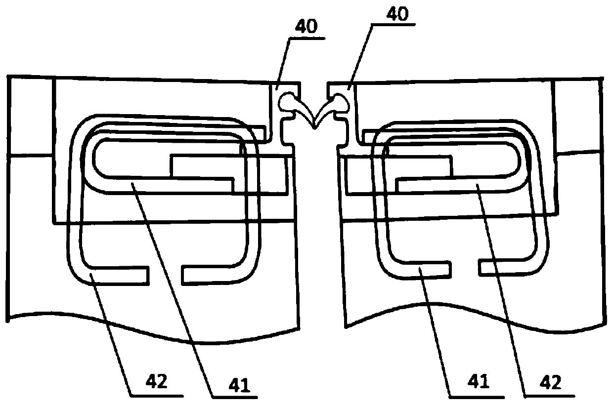
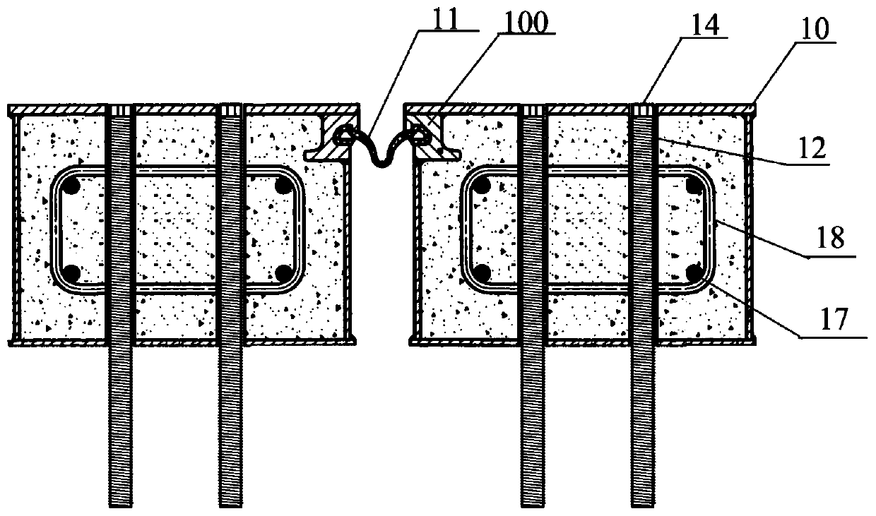
[0041] Self-stabilizing bridge telescopic device described in this embodiment, see figure 2, composed of symmetrically arranged bridge expansion device monomers, rubber strips 11 for bridge expansion and contraction are arranged between the symmetrically arranged bridge expansion device monomers, and the upper parts of the opposite sides of the symmetrically arranged bridge expansion device monomers 10 are arranged There is a special-shaped steel structure 100 for installing rubber strips 11, and the two sides of the rubber strips 11 are inserted into the special-shaped steel structure 100; the section of the special-shaped steel structure 100 is C-shaped; the bridge expansion device includes a box body 10, several first sleeves 12 arranged inside the box body 10, and vertical pins 14 arranged in the first sleeves 12, the inner side of the first sleeve 12 is provided with the inner side matching with the vertical pins 14 The upper part of the vertical pin 14 is threadedly con...

Embodiment 2

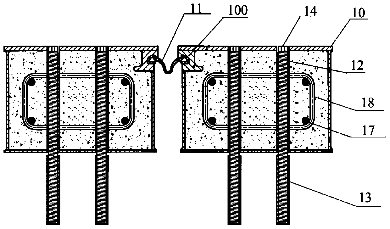
[0043] Self-stabilizing bridge telescopic device described in this embodiment, see image 3 , composed of symmetrically arranged bridge expansion device monomers, rubber strips 11 for bridge expansion and contraction are arranged between the symmetrically arranged bridge expansion device monomers, and the upper parts of the opposite sides of the symmetrically arranged bridge expansion device monomers 10 are arranged There is a special-shaped steel structure 100 for installing rubber strips 11, and the two sides of the rubber strips 11 are inserted into the special-shaped steel structure 100; the section of the special-shaped steel structure 100 is C-shaped; the bridge expansion device includes a box Body 10, several first sleeves 12 arranged inside the box body 10, vertical pins 14 and second sleeves 13 arranged in the first sleeve 12, the first sleeve 12 and the second sleeve 13 The inner side of the vertical pin 14 is provided with an internal thread that matches the vertica...

Embodiment 3

[0047] The self-stabilizing bridge expansion device described in this embodiment is composed of symmetrically arranged bridge expansion device monomers, and rubber strips 11 for bridge expansion and contraction are arranged between the symmetrically arranged bridge expansion device monomers. The upper part of the opposite side of the telescopic device unit 10 is provided with a special-shaped steel structure 100 for installing the rubber strip 11, and the two sides of the rubber strip 11 are inserted into the special-shaped steel structure 100; the cross-section of the special-shaped steel structure 100 is C-shaped The bridge telescopic device unit includes a box body 10, several first sleeves 12 arranged inside the box body 10, vertical pins 14 and second sleeves 13 arranged in the first sleeve 12, the first The inner side of a sleeve 12 and the second sleeve 13 is provided with an internal thread matched with the vertical pin 14, the top of the vertical pin 14 is threadedly c...


PUM


Abstract

The invention belongs to the technical field of bridge engineering parts, and particularly relates to a self-stabilizing bridge expansion and contraction device and an installation method thereof. Theself-stabilizing bridge expansion and contraction device is composed of symmetrically arranged bridge expansion and contraction device single-bodies, and a rubber strip for bridge expansion and contraction is arranged between the symmetrically arranged bridge expansion and contraction device single-bodies. Each bridge expansion and contraction device single-body comprises a box body, a pluralityof first sleeves arranged in the box body and vertical pins arranged in the first sleeves, internal threads matched with the vertical pins are arranged on the inner sides of the first sleeves, the upper parts of the vertical pins are connected with the first sleeves through threads, and the first sleeves vertically penetrate through the upper surface and the lower surface of the box bodies. The self-stabilizing bridge expansion and contraction device has the advantages of standardized quality, long service life, easy installation, short installation period, no nursing, convenient replacement and the like, and has wide market application prospect.

Description

technical field [0001] The invention belongs to the technical field of bridge engineering components, and in particular relates to a self-stabilizing bridge telescopic device and an installation method thereof. Background technique [0002] Prior art bridge telescoping device, see figure 1 , including a steel beam (40), the steel beam (40) is provided with a ring-shaped steel bar (41), and a plurality of pre-embedded steel bars (42) are pre-embedded on the bridge base. In the process of use, it is first necessary to precisely control the welding position, and weld the ring steel bar (41) of the bridge expansion device and the embedded anchor bar (42) one by one, support the formwork, and then pour high-strength concrete for no less than 14 days. During the maintenance period, the traffic is closed, and vehicles are allowed to pass after the maintenance period expires, that is, the installation of the bridge expansion device is completed. The existing bridge expansion devic...

Claims


Application Information

Patent Timeline
Patent Type & Authority Applications(China)
IPC IPC(8): E01D19/06
Inventor 穆雪野贾晓军丁智勇王伟张利权跃文刘盟王超
Owner 陕西融创交通科技有限公司
Why Eureka
Try Eureka