Eureka AIR delivers breakthrough ideas for toughest innovation challenges, trusted by R&D personnel around the world.

Shock wave focused ignition detonation burner and ignition detonation method thereof

A technology of shock wave focusing and detonation combustion, which is applied in the direction of machines/engines, rocket engine devices, jet propulsion devices, etc., can solve problems such as ignition instability, improve fuel utilization, enhance reliability, and simplify design and processing Effect

Active Publication Date: 2020-09-18
HUAZHONG UNIV OF SCI & TECH
View PDF5 Cites 0 Cited by
  • Summary
  • Abstract
  • Description
  • Claims
  • Application Information

AI Technical Summary

Problems solved by technology

[0004] Aiming at the above defects or improvement needs of the prior art, the present invention provides a shock wave focusing ignition detonation burner and its ignition method. The purpose is to adopt a dynamic and static double concave cavity shock focusing structure, which can effectively overcome the traditional shock Focus on ignition instability and reduce detonation tube layout space to improve fuel utilization

Method used


Image

  • Shock wave focused ignition detonation burner and ignition detonation method thereof
  • Shock wave focused ignition detonation burner and ignition detonation method thereof
  • Shock wave focused ignition detonation burner and ignition detonation method thereof

Examples


Embodiment Construction

[0026] In order to make the object, technical solution and advantages of the present invention clearer, the present invention will be further described in detail below in conjunction with the accompanying drawings and embodiments. It should be understood that the specific embodiments described here are only used to explain the present invention, not to limit the present invention. In addition, the technical features involved in the various embodiments of the present invention described below can be combined with each other as long as they do not constitute a conflict with each other.

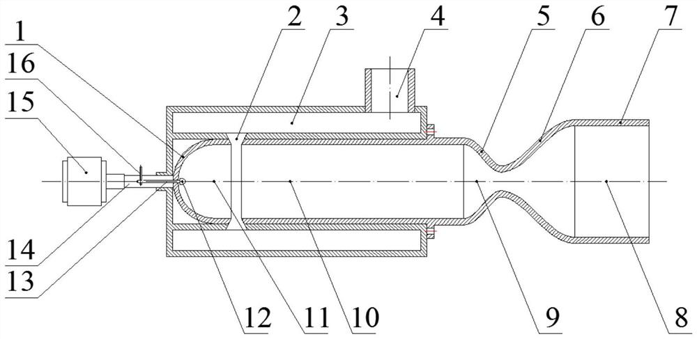
[0027]The specific structure of the burner in the present invention is as follows: comprising a gas collection guide chamber 3, a primary shock wave focusing chamber 11, a pre-combustion chamber 10, a secondary shock wave focusing chamber 9 and a detonation chamber 8, characterized in that the collection The air guide 3 chamber has a high-pressure air inlet 4 and an annular tapered jet nozzle 2;...


PUM


Abstract

The invention discloses an ignition and detonation combustor by utilizing shock wave focusing and an ignition and detonation method thereof, and belongs to the technical field of engines. According tothe combustor, a primary shock wave focusing chamber performs high-frequency reciprocating translational motion along with a dynamic concave cavity and is periodically connected and disconnected witha gas collecting flow guide cavity, generated shock waves are reflected in the concave cavity, focused to form a local high temperature and directly ignites combustible mixture to crack and oxidize macromolecular fuel in a high-pressure area, so that a large amount of easy-to-detonated activating groups and micromolecular gas are generated; and a secondary shock wave focusing chamber is reverselyarranged relative to the primary shock wave focusing chamber, the reflected shock waves in the primary shock wave focusing chamber are reflected again in the secondary shock wave focusing chamber, focused to form a three-wave structure to form a local high temperature and directly detonates detonation waves in the high-pressure area. The invention further provides an ignition and detonation method. According to the method, two-time shock wave focusing is adopted for ignition, so that the stability of the working process is effectively improved, and compared with a traditional shock wave focusing ignition mode, the method effectively enhances the high-frequency cyclic detonation characteristic.

Description

technical field [0001] The invention belongs to the technical field of engines, and more specifically relates to a shock wave focused ignition detonation combustor and an ignition and detonation method thereof. Background technique [0002] Pulse detonation engine is a new concept engine that uses high temperature and high pressure gas generated by pulse detonation waves to generate thrust. The pulse detonation engine has the advantages of simple structure, light weight, high thrust-to-weight ratio, and high combustion efficiency. Since the advent of this type of engine, it has attracted the interest of many researchers. Whether the potential of the pulse detonation engine can be brought into play depends on the high-frequency and reliable detonation shock wave. [0003] In the past few decades, people have done a lot of research work on detonation initiation technology. But at present, neither the direct detonation nor the deflagration-to-detonation (DDT) detonation metho...

Claims


Application Information

Patent Timeline
Patent Type & Authority Patents(China)
IPC IPC(8): F02K9/95F02K9/62
CPCF02K9/62F02K9/95
Inventor 赵家权吴杰
Owner HUAZHONG UNIV OF SCI & TECH
Why Eureka
Eureka Blog
Learn More