Supercharge Your Innovation With Domain-Expert AI Agents!

Video management control system used under field flexible condition

A technology for video management and control systems, applied in non-rotational vibration suppression, cleaning methods using tools, supporting machines, etc. The effect of preventing damage

Inactive Publication Date: 2019-06-07
刘振军
View PDF7 Cites 1 Cited by
  • Summary
  • Abstract
  • Description
  • Claims
  • Application Information

AI Technical Summary

Problems solved by technology

[0002] As we all know, the video management control system used under field maneuvering conditions is an auxiliary system for image display during field operations, and it has been widely used in the field of video equipment; the existing field maneuvering conditions used The video management control system includes a display screen, a base plate and wires. A frame is arranged outside the display screen, the bottom of the frame is connected to the central area of ​​the top of the base plate, and the wires are electrically connected to the display screen; the existing video management control system used under field maneuvering conditions When the system is in use, the display screen is installed at the required position through the bottom plate, and the display screen is electrically connected to the external processing system through wires. Under field maneuvering conditions, the image information is displayed through the display screen; the existing video used under field maneuvering conditions During the use of the management control system, it was found that because the display screen is in the field maneuvering condition, there will be a large vibration during the movement, and the vibration will easily cause serious damage to the display screen, resulting in poor reliability

Method used


Image

  • Video management control system used under field flexible condition
  • Video management control system used under field flexible condition
  • Video management control system used under field flexible condition

Examples


Embodiment Construction

[0017] The specific implementation manners of the present invention will be further described in detail below in conjunction with the accompanying drawings and embodiments. The following examples are used to illustrate the present invention, but are not intended to limit the scope of the present invention.

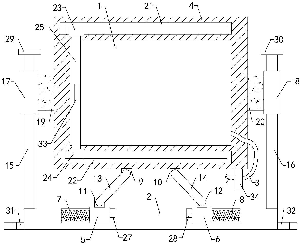
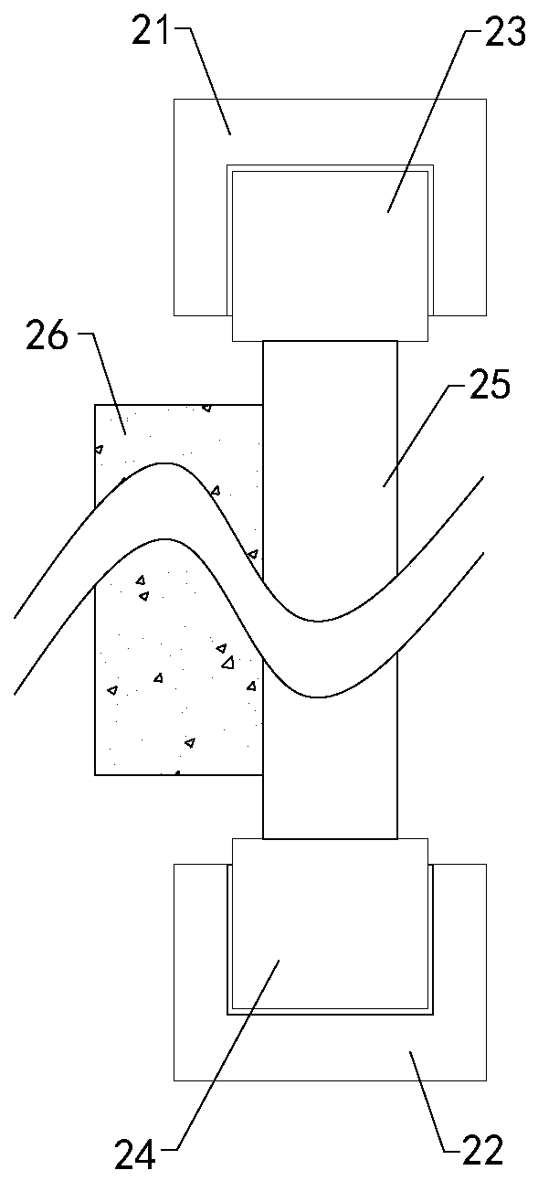
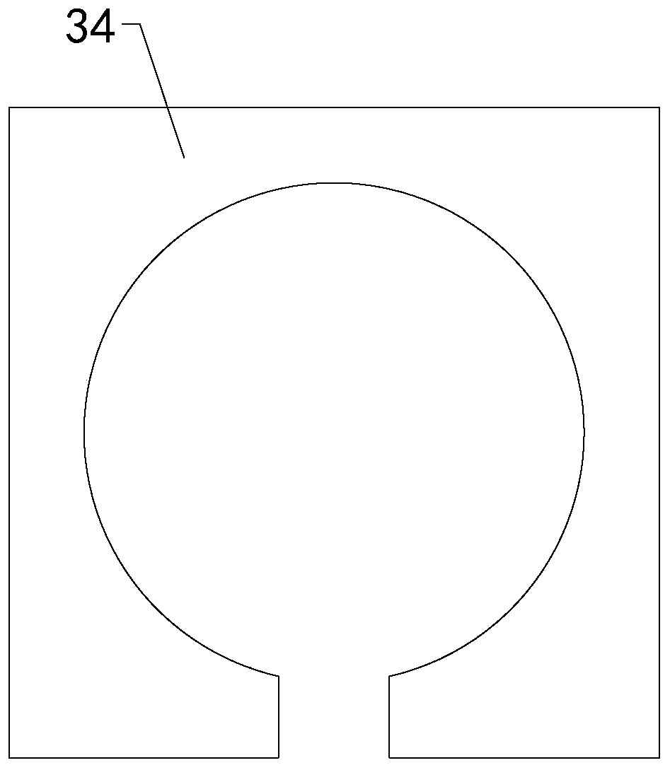
[0018] Such as Figure 1 to Figure 3 As shown, a video management and control system used under a field maneuvering condition of the present invention includes a display screen 1, a bottom plate 2 and a wire 3, a frame 4 is arranged outside the display screen 1, and the wire 3 is electrically connected to the display screen 1; Including left slider 5, right slider 6, left spring 7, right spring 8, first left ear plate 9, first right ear plate 10, second left ear plate 11, second right ear plate 12, left action rod 13, right action rod 14, left support rod 15, right support rod 16, left sliding plate 17, right sliding plate 18, left connecting block 19 and right connecting...


PUM


Abstract

The invention relates to the technical scheme of video equipment subsystems, in particular to a video management control system used under a field flexible condition. A display screen can be bufferedwell when vibration is generated in the motion process, damage of vibration to the display screen is reduced, and the use reliability is improved. The video management control system comprises the display screen, a bottom plate and a guide wire. A frame is arranged outside the display screen. A left sliding block, a right sliding block, a left spring, a right spring, a first left lug plate, a first right lug plate, a second left lug plate, a second right lug plate, a left action rod, a right action rod, a left supporting rod, a right supporting rod, a left sliding plate, a right sliding plate,a left connecting block and a right connecting block. A left sliding groove and a right sliding groove are formed in the left half area and the right half area of the top end of the bottom plate correspondingly. A left sliding hole and a right sliding hole are longitudinally formed in the center area of the top end of the left sliding plate and the center area of the top end of the right slidingplate correspondingly.

Description

technical field [0001] The invention relates to the technical field of video equipment accessory systems, in particular to a video management control system used under field maneuvering conditions. Background technique [0002] As we all know, the video management control system used under field maneuvering conditions is an auxiliary system for image display during field operations, and it has been widely used in the field of video equipment; the existing field maneuvering conditions used The video management control system includes a display screen, a base plate and wires. A frame is arranged outside the display screen, the bottom of the frame is connected to the central area of ​​the top of the base plate, and the wires are electrically connected to the display screen; the existing video management control system used under field maneuvering conditions When the system is in use, the display screen is installed at the required position through the bottom plate, and the disp...

Claims


Application Information

Patent Timeline
Patent Type & Authority Applications(China)
IPC IPC(8): F16M11/04F16M11/24F16F15/04F16F15/08B08B1/00
Inventor 刘振军苗增良王振祥汪晓红张铁梁
Owner 刘振军
Features
  • R&D
  • Intellectual Property
  • Life Sciences
  • Materials
  • Tech Scout
  • Unparalleled Data Quality
  • Higher Quality Content
  • 60% Fewer Hallucinations
Learn More