Jet type supercooling refrigeration system

A refrigeration system and jet technology, applied in subcoolers, refrigerators, refrigeration components, etc., can solve the problems of increasing input cost and operating cost, and achieve the effect of reducing input cost, sufficient cooling process, and large heat exchange temperature difference

Pending Publication Date: 2019-06-07
TIANJIN UNIV OF COMMERCE
View PDF0 Cites 5 Cited by
  • Summary
  • Abstract
  • Description
  • Claims
  • Application Information

AI Technical Summary

Problems solved by technology

For a large-scale refrigeration system, adding a subcooling refrigeration device means adding a small refrigeration system to exchange heat between the evaporator and the condenser outlet of the large refrigeration system to achieve a greater degree of subcooling. This method is due to the addition of a set of Small refrigeration unit increases input and operating costs

Method used


Image

  • Jet type supercooling refrigeration system
  • Jet type supercooling refrigeration system

Examples


Embodiment 1

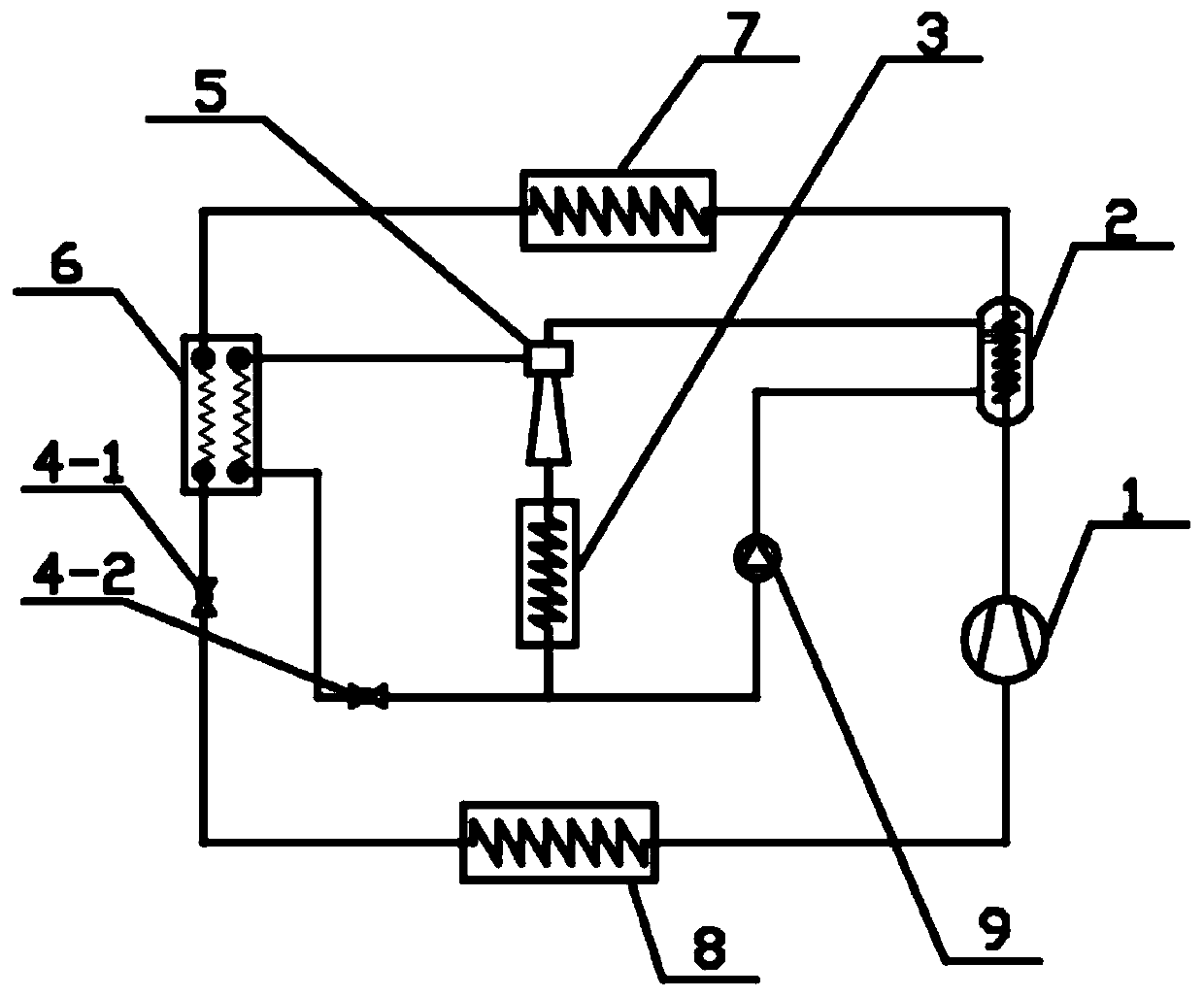
[0022] The schematic diagram of the injection type subcooling refrigeration system of the present invention is as follows: figure 1 As shown, it includes a main refrigeration cycle and an ejector subcooling refrigeration cycle. The main refrigeration cycle is composed of the compressor 1, the tube side channel of the generator 2, the main condenser 7, and the subcooling side channel of the subcooler 6. , the first throttling device 4 - 1 and the evaporator 8 are connected in sequence and then return to the closed cycle of the suction port of the compressor 1 . The ejector type subcooling refrigeration cycle includes the ejector 5, branch condenser 3, second throttling device 4-2 and circulation pump 9, the high-pressure fluid inlet of the ejector 5 is connected to the shell side of the generator 2 The outlet of the ejector 5 is connected to the inlet of the branch condenser 3, and the outlet of the branch condenser 3 is divided into two paths, one of which passes through the s...

Embodiment 2

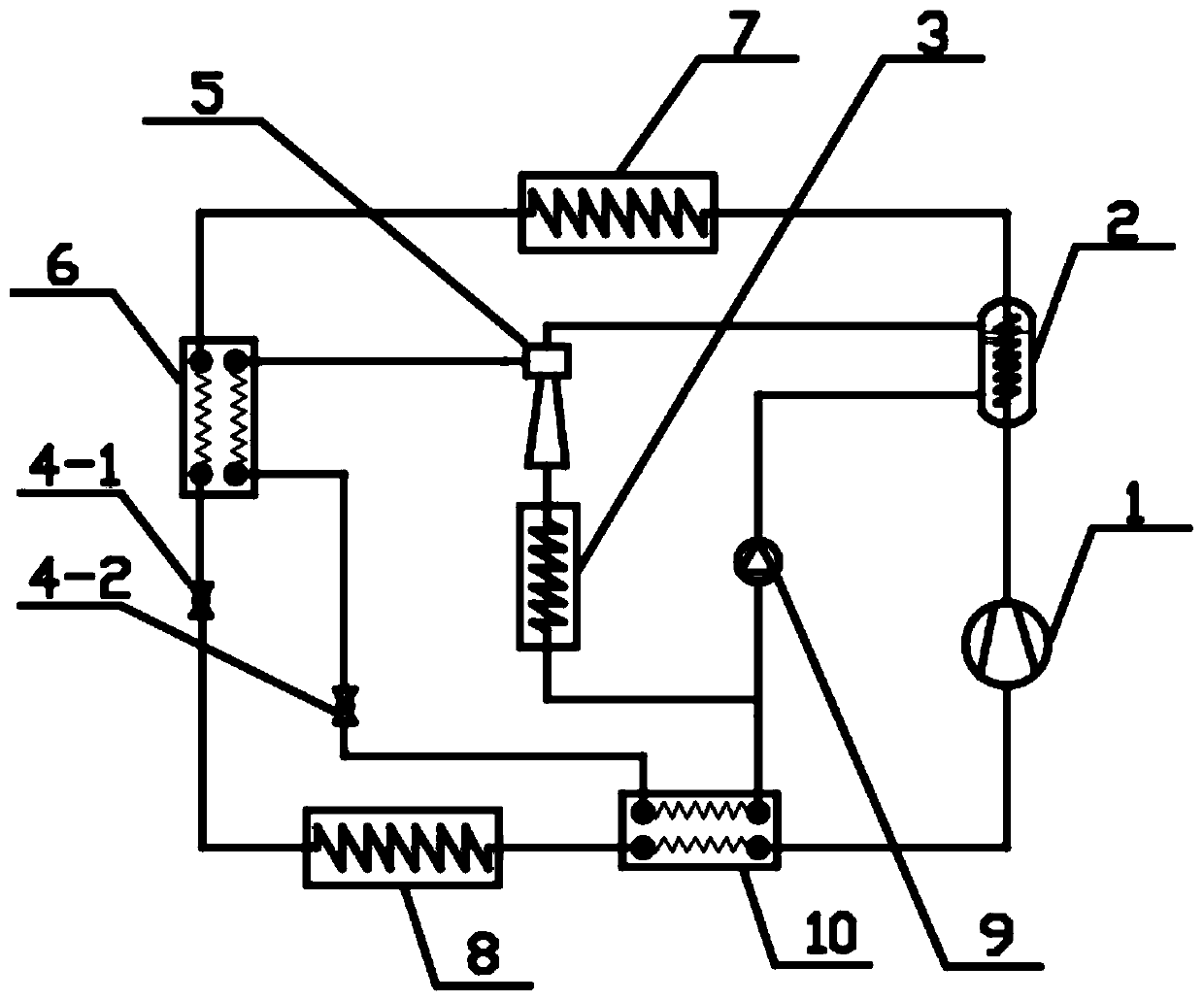
[0025] The schematic diagram of the injection type subcooling refrigeration system with superheater of the present invention is as figure 2 Shown, including the main refrigeration cycle and injection subcooling refrigeration cycle. The main refrigeration cycle is composed of the compressor 1, the tube side passage of the generator 2, the main condenser 7, the subcooling side passage of the subcooler 6, the first throttling device 4-1, the evaporator 8 and the superheating The inlet and outlet of the superheated side of the device 10 are connected in sequence and then return to the closed cycle of the suction port of the compressor 1. The ejector type subcooling refrigeration cycle includes the ejector 5, branch condenser 3, second throttling device 4-2 and circulation pump 9, the high-pressure fluid inlet of the ejector 5 and the shell of the generator 2 The side outlet is connected, the outlet of the ejector 5 is connected to the inlet of the branch condenser 3, the outlet ...


PUM


Abstract

The invention discloses a jet type supercooling refrigeration system, and aims at providing a refrigeration system capable of obtaining a large degree of supercooling and low operation cost. The jet type supercooling refrigeration system comprises a main refrigeration cycle and a jet subcooling refrigeration cycle; the cooling heat of the high temperature gas of the compressor exhaust port in themain refrigeration cycle drives an injector in the jet subcooling refrigeration cycle. The refrigeration system can obtain a large degree of subcooling, and the high-pressure refrigerant liquid in a generator is heated by the cooling heat of the high-temperature gas of the compressor exhaust port, so that the jet supercooling cycle can use the waste heat effectively; without other energy input, the operation cost is reduced. Meanwhile, the refrigerant entering a main condenser has a lower temperature, the space occupied by the condenser is reduced, the cooling process is more sufficient, the energy efficiency of the system is improved effectively; and the service life of the compressor is prolonged.

Description

technical field [0001] The invention relates to the technical field of refrigeration, and more specifically relates to a refrigeration system with a refrigerant cooling heat-driven injector with a compression exhaust port for liquid subcooling. Background technique [0002] In the practical application of a single-stage compression vapor refrigeration cycle, the thermal perfection of the cycle can be improved by measures such as liquid subcooling, vapor superheating, and the resulting heat recovery cycle. The traditional liquid subcooling process can be realized by increasing the area of ​​the condenser. Since the heat exchange medium in this way does not change, it is necessary to greatly increase the heat exchange area of ​​the condenser to reduce the heat exchange temperature difference, in order to achieve a relatively small condenser outlet. Low liquid temperature, the degree of subcooling obtained by relying only on the condenser to achieve subcooling has a certain lim...

Claims


Application Information

Patent Timeline
Patent Type & Authority Applications(China)
IPC IPC(8): F25B9/08F25B40/02
Inventor 杨永安李瑞申谷沅橙
Owner TIANJIN UNIV OF COMMERCE
Why Eureka
Try Eureka