
Energy-saving environment-friendly type permanent magnet speed regulation device

A permanent magnet speed regulation, energy saving and environmental protection technology, applied in electromechanical devices, cooling/ventilation devices, permanent magnet clutches/brakes, etc. Power saving effect

Active Publication Date: 2019-06-07
MAANSHAN LANXIN ENVIRONMENTAL PROTECTION TECH CO LTD
View PDF1 Cites 9 Cited by
  • Summary
  • Abstract
  • Description
  • Claims
  • Application Information

AI Technical Summary

Problems solved by technology

[0004] The purpose of the present invention is to solve the problem that the permanent magnet rotor and the conductor rotor in the speed regulating device in the prior art are prone to idling with each other, so that the driving device cannot effectively transmit the torque, wasting electric energy, and the permanent magnet speed regulating device is exposed , It is easy to entangle workers' clothes when rotating, and there is a dangerous problem, and an energy-saving and environment-friendly permanent magnet speed control device is proposed

Method used

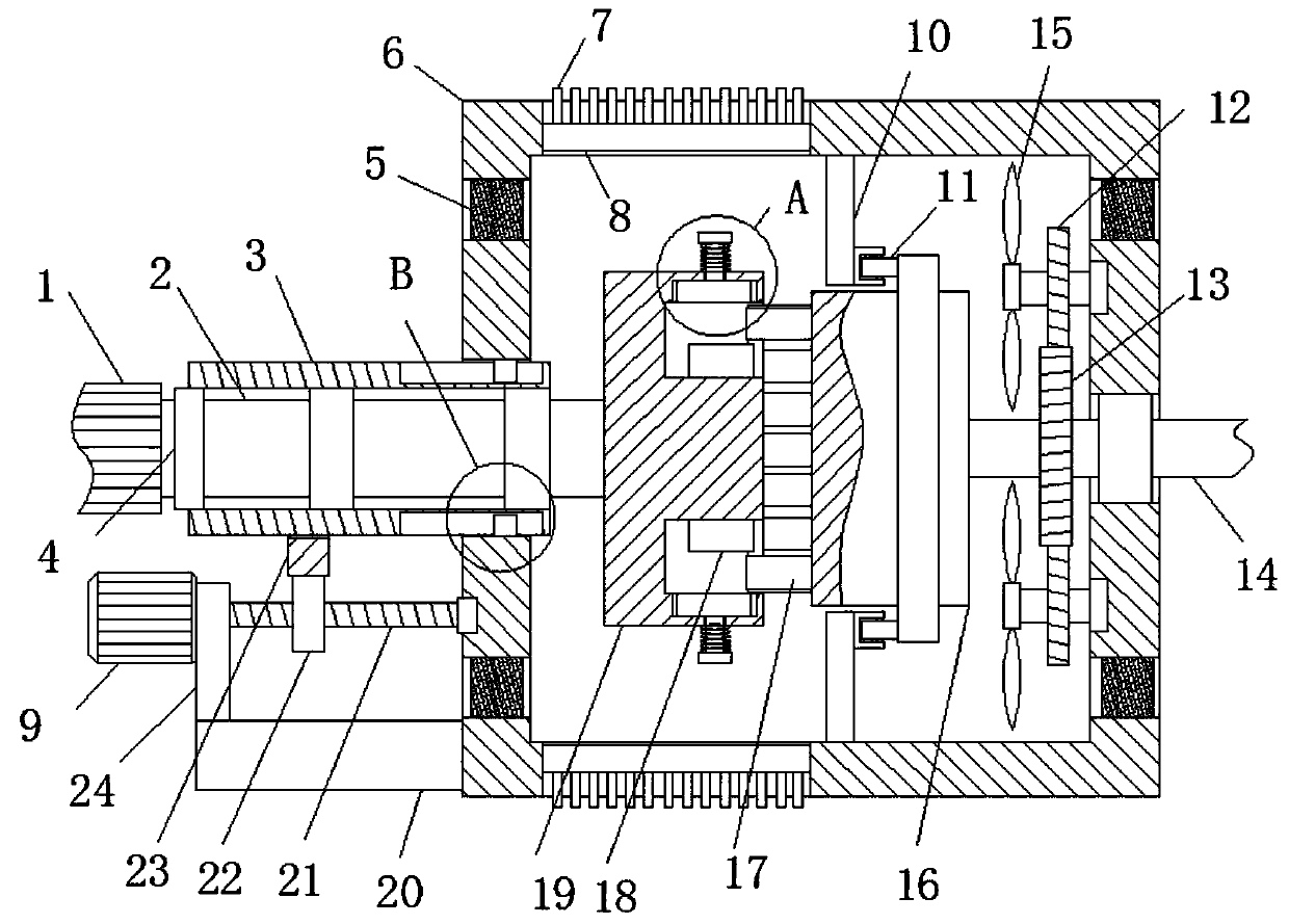

Image

  • Energy-saving environment-friendly type permanent magnet speed regulation device
  • Energy-saving environment-friendly type permanent magnet speed regulation device
  • Energy-saving environment-friendly type permanent magnet speed regulation device

Examples


Embodiment Construction

[0025] The technical solutions in the embodiments of the present invention will be clearly and completely described below in conjunction with the accompanying drawings in the embodiments of the present invention. Obviously, the described embodiments are only a part of the embodiments of the present invention, rather than all the embodiments.

[0026] In the description of the present invention, it should be understood that the terms "upper", "lower", "front", "rear", "left", "right", "top", "bottom", "inner", " The orientation or positional relationship indicated by "outside" is based on the orientation or positional relationship shown in the drawings, and is only for the convenience of describing the present invention and simplifying the description, and does not indicate or imply that the device or element referred to must have a specific orientation to The specific azimuth structure and operation cannot be understood as a limitation of the present invention.

[0027] Reference ...


PUM


Abstract

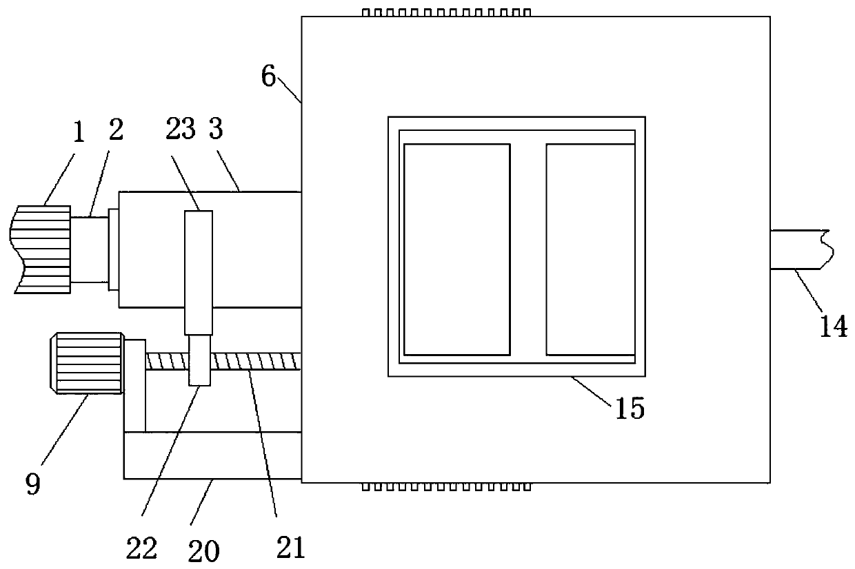
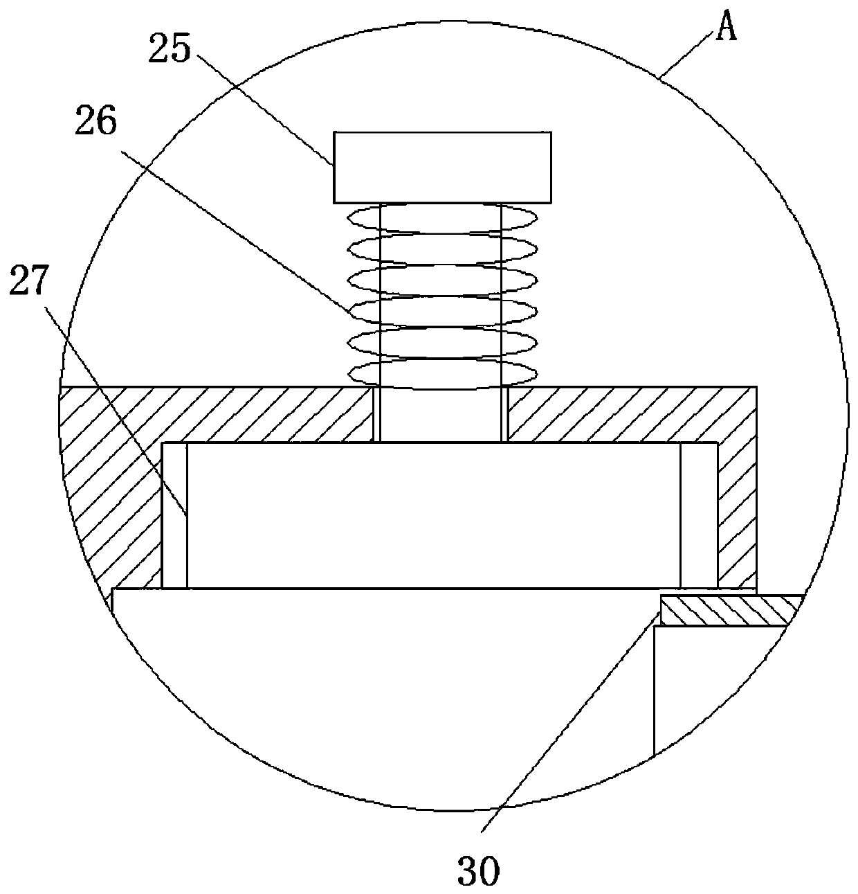
The invention relates to the technical field of driving speed regulation, and discloses an energy-saving environment-friendly type permanent magnet speed regulation device; the energy-saving environment-friendly type permanent magnet speed regulation device comprises a shell, wherein a rectangular pipe is transversely connected with the left of the shell through a rectangular through hole in a sliding and sleeving mode, and an output shaft is arranged in the rectangular pipe, and two first rolling shafts are fixedly connected to the shaft wall of the output shaft; the outer rings of two firstrolling bearings are fixedly connected with the inner wall of the rectangular pipe, and one end of the output shaft penetrates through the rectangular pipe and is fixedly connected with a mounting block; an annular groove is formed in the right side of the mounting block; a plurality of first magnets are uniformly and fixedly connected to one side of the annular groove, wherein the plurality of first magnets are annularly distributed; and a transverse plate is fixedly connected to the lower end of the left side of the shell. According to the device, the transmission torque between a permanentmagnet rotor and a conductor rotor in the speed regulation device can be effectively increased, so that the driving device is not easy to perform idle rotation, electric energy is saved, and when thepermanent magnet speed regulation device works, the clothes of workers are not prone to being wound so as to avoid dangers.

Description

Technical field [0001] The invention relates to the technical field of drive speed regulation, in particular to an energy-saving and environment-friendly permanent magnet speed regulation device. Background technique [0002] Speed ​​control device is used to reduce the non-periodical speed fluctuation of some machines. The machine speed can be maintained at a fixed value or close to the set value. Unlike electric motors, hydraulic turbines, steam turbines, gas turbines and internal combustion engines, their output torque cannot automatically adapt to their own load changes, so when the load changes, the units driven by them will lose stability. This type of unit must be equipped with a governor so that it can establish an adaptive relationship between the load and the energy supply at any time as the load and other conditions change, so as to ensure the normal operation of the unit. The theory and design issues of governor are the research content of mechanical dynamics. Perma...

Claims


Application Information

Patent Timeline
Patent Type & Authority Applications(China)
IPC IPC(8): H02K49/10H02K9/06
Inventor 宗寒李凯
Owner MAANSHAN LANXIN ENVIRONMENTAL PROTECTION TECH CO LTD
Learn More