Server air-cooled and high-efficiency heat dissipating device
A technology of cooling device and server, applied in the direction of cooling/ventilation/heating transformation, etc., can solve the problems of uneven air-cooled heat dissipation and poor air-cooled heat dissipation effect, and achieve the effect of improving the heat dissipation effect and the contact area.
- Summary
- Abstract
- Description
- Claims
- Application Information
AI Technical Summary
Problems solved by technology
Method used
Image
Examples
Embodiment 1
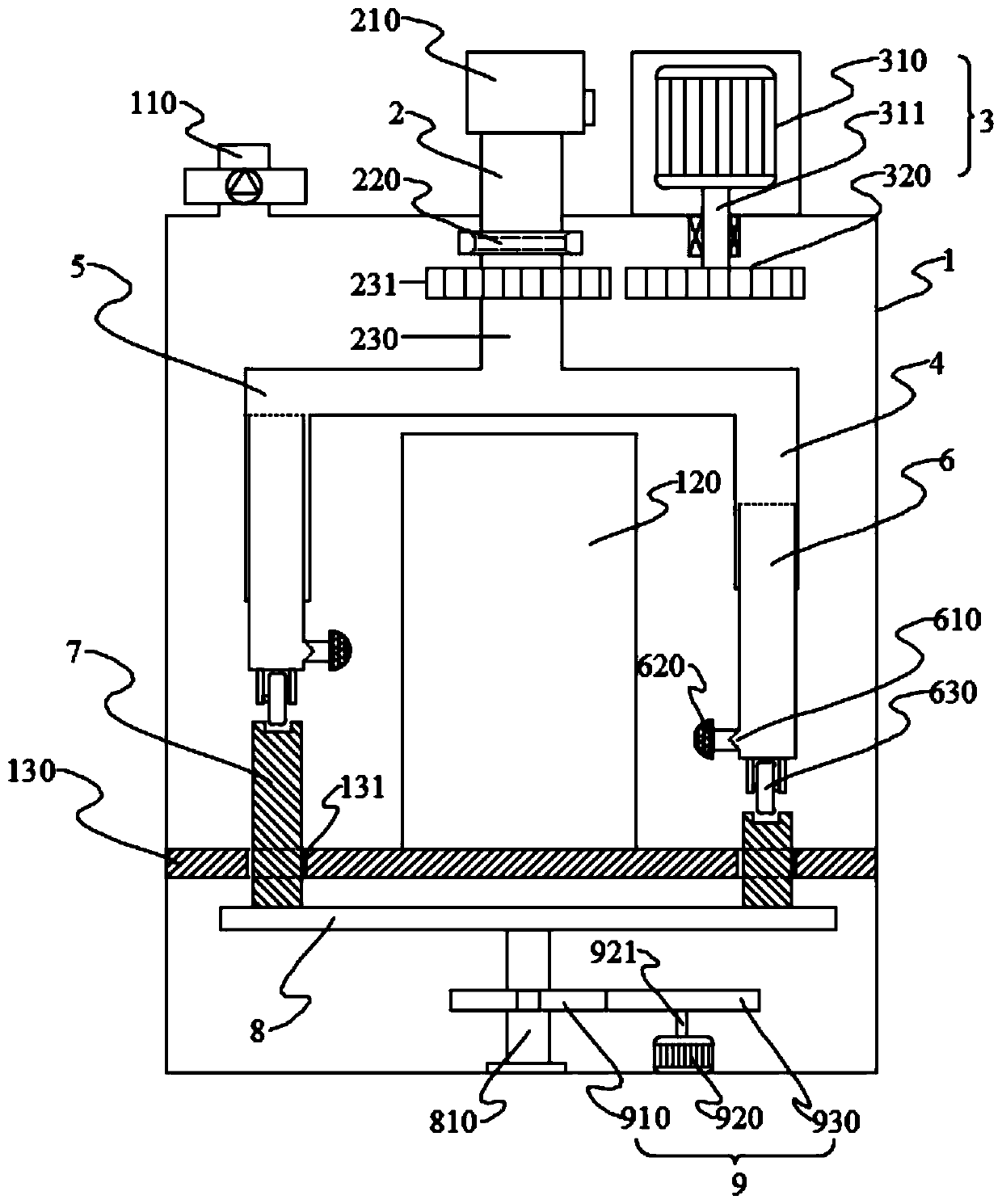
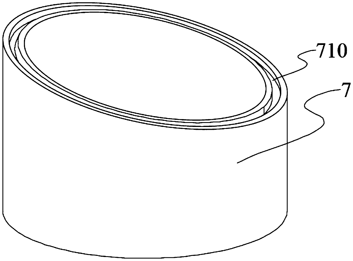
[0029] The server 120 air-cooled high-efficiency heat dissipation device of the present invention includes a box body 1. A placement plate 130 is arranged inside the box body 1. The server 120 is arranged on the upper end of the placement plate 130. An exhaust pipe is arranged on the upper end of the box body 1. It is characterized in that, The upper end of the box body 1 is provided with an air inlet pipe 2, the upper end of the air inlet pipe 2 is connected with an exhaust fan 210, the lower end of the air inlet pipe 2 is connected with a connecting ring 220, and the lower end of the connecting ring 220 is rotated to be provided with a guide pipe 230, and the upper end of the air guide pipe 230 is sleeved There is a driven wheel 231, the driven wheel 231 is engaged with the driving device 3, the lower end of the guide tube 230 is communicated with the first shunt tube 4, the first shunt tube 4 is provided with a guide tube 6, and the side wall of the lower end of the guide tub...
Embodiment 2
[0032]This embodiment is further optimized on the basis of Embodiment 1 as follows: the lower end of the flow guide pipe 230 is also communicated with a second shunt pipe 5, the second shunt pipe 5 communicates with the first shunt pipe 4, and the second shunt pipe 5 is also provided with a guide tube 6 , the first shunt pipe 4 and the second shunt pipe 5 are both L-shaped, and the long side of the L-shape is located outside the server 120 .
[0033] After adopting this technical scheme, by adding the second branch pipe 5, the contact between the cold air and the different positions of the outer wall of the server 120 is improved at the same time, the contact area is increased, and the heat dissipation effect of the server 120 is further improved. The first branch pipe 4 and the second air flow The structure of the pipes is the same, and they are only distinguished for the convenience of people's description. The first branch pipe 4 and the second branch pipe 5 are L-shaped, an...
Embodiment 3
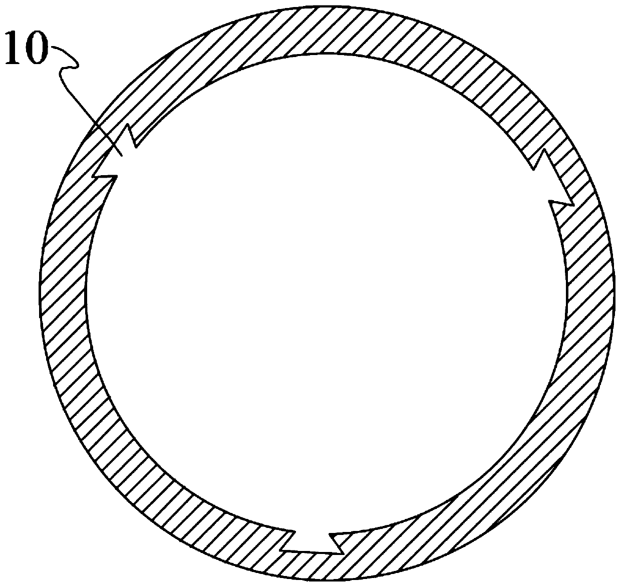
[0035] This embodiment is further optimized on the basis of Embodiment 2 as follows: the outer wall of the guide tube 6 is provided with at least two dovetail blocks 11, and the inner walls of the first shunt pipe 4 and the second shunt pipe 5 are provided with dovetail blocks. 11 Matching dovetail slots 10.
[0036] After adopting this technical scheme, by setting the dovetail block 11 on the outer wall of the flow guide tube 6, and setting the dovetail groove 10 on the inner wall of the first flow pipe 4 and the second flow pipe 5, it is ensured that the flow guide tube 6 is connected between the first flow pipe and the second flow pipe. The positioning of the lift in the second shunt tube 5 ensures that the first shunt tube 4 and the second shunt tube 5 drive the guide tube 6 to rotate, and the guide tube 6 will not rotate around itself, ensuring that the roller 630 is located in the limit groove 710 .
PUM
 Abstract
Description
Claims
Application Information
 - R&D
- Intellectual Property
- Life Sciences
- Materials
- Tech Scout
- Unparalleled Data Quality
- Higher Quality Content
- 60% Fewer Hallucinations
Browse by: Latest US Patents, China's latest patents, Technical Efficacy Thesaurus, Application Domain, Technology Topic, Popular Technical Reports.
© 2025 PatSnap. All rights reserved.Legal|Privacy policy|Modern Slavery Act Transparency Statement|Sitemap|About US| Contact US: help@patsnap.com


