Supercharge Your Innovation With Domain-Expert AI Agents!

Gas-liquid synchronous mixing and puffing device and ice cream machine comprising same

A puffing device, gas-liquid technology, applied in the direction of frozen desserts, food science, application, etc., can solve the problems of low puffing rate, difficult puffing rate, poor mixing effect, etc., and achieve the effect of uniform puffing and delicate taste

Pending Publication Date: 2019-06-11
兰云科技(广州)有限责任公司
View PDF0 Cites 9 Cited by
  • Summary
  • Abstract
  • Description
  • Claims
  • Application Information

AI Technical Summary

Problems solved by technology

[0003] In order to achieve the ideal effect of puffing ice cream and milkshakes, the existing ice cream machines and milkshake making machines basically install an puffing device at the position where the bottom of the raw material tank is connected to the feed pipe. Feed hole, the slurry enters the feed pipe through the feed hole, and then flows into the refrigeration cylinder. There is a vent hole on the upper end of the puffing device. When the slurry flows into the refrigeration cylinder, the air enters the refrigeration cylinder from the vent hole on the upper end of the puffing device. , the slurry is stirred and mixed with air, and frozen to make ice cream and milkshake with a certain expansion rate, but this kind of expansion device is greatly affected by the viscosity of the slurry and particles, and it is easy to be blocked by the particles in the slurry. The puffing rate of ice cream and milkshake is difficult to be accurately controlled, and in the refrigeration cylinder, the air and slurry liquid are mixed and stirred in a free-flowing state. The mixing effect of air and slurry liquid is poor, and ice cream and milkshake cannot Achieve better puffing effect, uneven puffing, low puffing rate, poor taste of ice cream and milkshake, not soft and smooth enough

Method used


Image

  • Gas-liquid synchronous mixing and puffing device and ice cream machine comprising same
  • Gas-liquid synchronous mixing and puffing device and ice cream machine comprising same
  • Gas-liquid synchronous mixing and puffing device and ice cream machine comprising same

Examples


Embodiment Construction

[0026] The present invention will be described in further detail below in conjunction with the accompanying drawings.

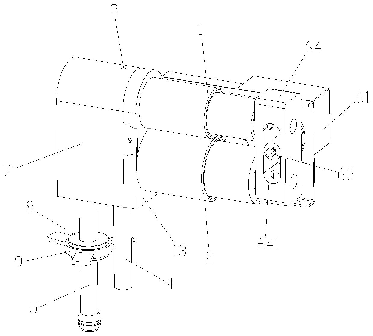
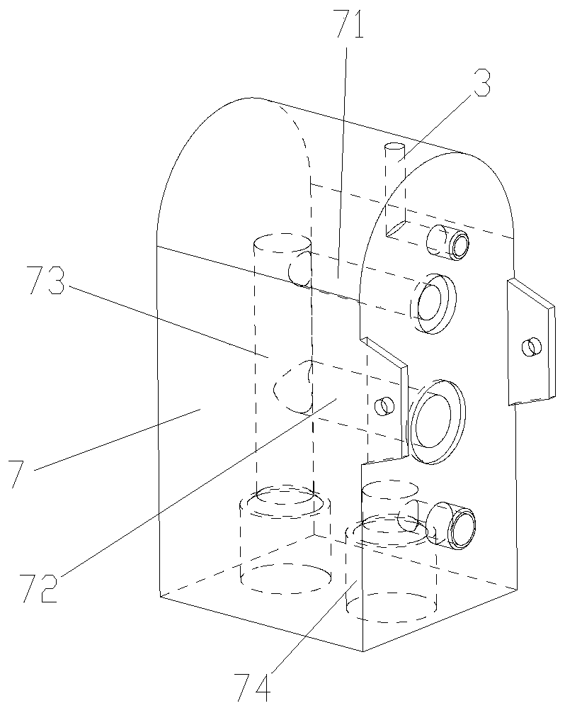
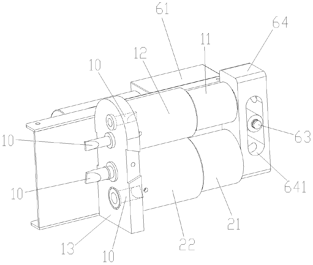
[0027] Figure 1 to Figure 8 It schematically shows the structure of a gas-liquid synchronous mixing and expanding device according to an embodiment of the present invention.

[0028] Such as Figure 1 to Figure 8 As shown, the gas-liquid synchronous mixing and puffing device includes a piston cylinder A1, a piston cylinder B2, an air intake passage 3, a feed pipe 4, a discharge pipe 5, a driving device and a one-way valve 10. In addition, the gas-liquid synchronous mixing and expanding device may further include a connecting block 7 , a pressure relief member 8 , a pressure relief ring 9 and a fixing plate 13 .

[0029] Such as figure 1 and image 3 As shown, the left end of the piston cylinder A1 (i.e. the cylinder body A12) and the left end of the piston cylinder B2 (i.e. the cylinder body B22) are all installed on one side of the fixed plate 13, and t...


PUM


Abstract

The invention discloses a gas-liquid synchronous mixing and puffing device and an ice cream machine comprising the same. The device comprises a piston cylinder A, a piston cylinder B, an air inlet channel, a feeding pipe, a discharging pipe and a driving device, under the action of the driving device; the piston cylinder A can pump outside air into a cylinder block A; meanwhile, the piston cylinder B can pump the slurry in a raw material cylinder into a cylinder block B; under the continuous action of the driving device, the piston cylinder A can inject air in the cylinder block A into the discharging pipe, meanwhile, the piston cylinder B can inject the slurry in the cylinder block B into the discharging pipe; air and slurry are synchronously injected into the discharging pipe; under thethrust action of a piston rod A and a piston rod B; air and the slurry can be fully mixed in the discharging pipe, so that the ice cream and the milkshake achieve a relatively good puffing effect, thewhole puffing device is basically not influenced by the viscosity and the particles of the slurry and is not easily blocked by the particles in the slurry, and the puffing rate of the ice cream and the milkshake can be relatively accurately controlled.

Description

technical field [0001] The invention relates to a gas-liquid synchronous mixing and puffing device and an ice cream machine comprising the same. Background technique [0002] When making ice cream and milkshake, the puffing rate has a very important influence on the quality and taste of ice cream and milkshake. The milkshake becomes a loose product with a good appearance and a smooth and smooth taste. [0003] In order to achieve the ideal effect of puffing ice cream and milkshakes, the existing ice cream machines and milkshake making machines basically install an puffing device at the position where the bottom of the raw material tank is connected to the feed pipe. Feed hole, the slurry enters the feed pipe through the feed hole, and then flows into the refrigeration cylinder. There is a vent hole on the upper end of the puffing device. When the slurry flows into the refrigeration cylinder, the air enters the refrigeration cylinder from the vent hole on the upper end of th...

Claims


Application Information

Patent Timeline
IPC IPC(8): A23G9/20A23G9/22
Inventor 凃汉杰
Owner 兰云科技(广州)有限责任公司
Features
  • R&D
  • Intellectual Property
  • Life Sciences
  • Materials
  • Tech Scout
  • Unparalleled Data Quality
  • Higher Quality Content
  • 60% Fewer Hallucinations
Learn More