Supercharge Your Innovation With Domain-Expert AI Agents!

Umbrella-shaped distributed ornithopter

A flapping aircraft and a technology for an aircraft, applied in the field of aircraft, can solve problems such as small load capacity

Inactive Publication Date: 2019-06-11
周承岗
View PDF0 Cites 0 Cited by
  • Summary
  • Abstract
  • Description
  • Claims
  • Application Information

AI Technical Summary

Problems solved by technology

[0003] The purpose of the present invention is to provide a flapping-wing aircraft, its wings are distributed in an umbrella shape around, and the number of wings is increased by making full use of the space, so that the total area of ​​the wings is increased to improve the load capacity, and overcome the disadvantages of the existing flapping-wing aircraft. The disadvantage of less load capacity due to the limitation of wing material, while also achieving more flight maneuvers

Method used


Image

  • Umbrella-shaped distributed ornithopter
  • Umbrella-shaped distributed ornithopter
  • Umbrella-shaped distributed ornithopter

Examples


Embodiment Construction

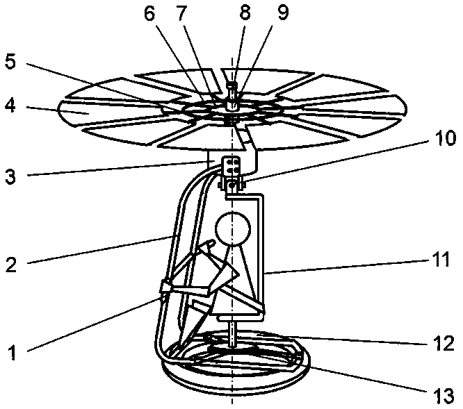
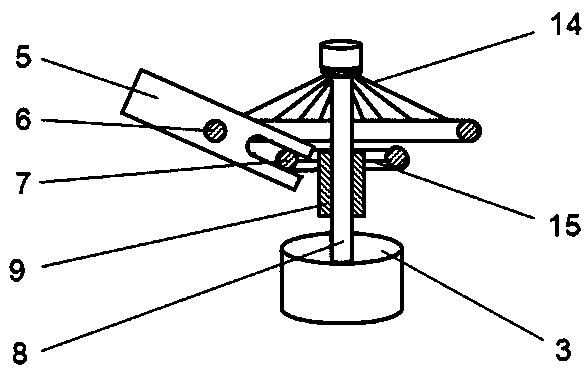
[0019] figure 1 , figure 2 Shown is the embodiment that the wing swings up and down, the frame 2 is fixedly connected with the mechanical cabin 3, the central axis 8 is fixedly connected with the mechanical cabin 3, the static ring 6 is fixedly connected with the central axis 8 through the spokes 14, and the moving ring 7 is fixedly connected with the central axis 8 through the spokes. 15 is fixedly connected with the slip ring 9 that can slide axially along the central axis 8, the wing 4 is connected with the swing rod 5 and is radially distributed with the central axis 8 as the center, the swing rod 5 is connected with the static ring 6 in rotation and connected with the dynamic The ring 7 is rotatably connected and can slide longitudinally. When the slip ring 9 slides up and down along the central axis 8, it can drive the wing 4 to swing up and down to generate thrust; the types of the wing 4 include but are not limited to thin shell type, one-way air hole type , inverted...


PUM


Abstract

The invention provides an umbrella-shaped distributed ornithopter. Wings of the umbrella-shaped distributed ornithopter are symmetrically distributed in the mode of radiating to the periphery from thecenter, the number of the wings is increased through full use of the space, the total area of the wings is increased, so that loading capacity is improved, the defect that an existing ornithopter issmall in loading capacity due to the limitation of a wing material is overcome, and meanwhile more complex flight actions are achieved. An umbrella-shaped propelling device is jointly composed of themultiple wings (4) of the umbrella-shaped distributed ornithopter, the course can be changed through adjustment of the overall gravity center of the ornithopter and propelling of the relative positionof the geometric center of the umbrella-shaped propelling device, or the course can be changed through adjustment of the swing amplitude or frequency of the wing (4) in a certain direction, or the direction or the size of the circumferential resultant force of the wings (4) can be changed through adjustment of the circumferential inclination angle of the wings (4) so that aerial autorotation of the ornithopter can be achieved or prevented, and the actions of vertical take-off and landing, hovering, pivot steering, horizontal 360-degree flight, steering during flight, parking autorotation landing and the like can be achieved.

Description

technical field [0001] The invention relates to an aircraft. Background technique [0002] The wings of a flapping-wing aircraft generally move back and forth. The higher the frequency, the greater the inertial loss of energy, and the effect of high-frequency alternating stress and the sharp increase of stress at the moment of round-trip turning have higher requirements on material properties. Under the given drag coefficient, Reynolds number and other related conditions, it is more beneficial to increase the load capacity. Generally, it is more beneficial to increase the total wing area than to increase the flapping frequency. However, the current flapping aircraft often imitates flying birds or insects in structure. The wings are only symmetrically distributed on the left and right sides, the space utilization rate is low, and the number of wings is small. To increase the total area of ​​the wings, it is necessary to increase the area of ​​the single wing, especially to in...

Claims


Application Information

Patent Timeline
Patent Type & Authority Applications(China)
IPC IPC(8): B64C33/02B64C33/00
Inventor 周承岗
Owner 周承岗
Features
  • R&D
  • Intellectual Property
  • Life Sciences
  • Materials
  • Tech Scout
  • Unparalleled Data Quality
  • Higher Quality Content
  • 60% Fewer Hallucinations
Learn More