
Backstitch structure of sewing machine

A sewing machine and reverse sewing technology, which is applied to sewing machine components, sewing machine control devices, sewing equipment, etc., can solve the problems of large electromagnet driving force, high requirements for electromagnet use, and small holding torque, so as to improve torque transmission efficiency, The effect of reducing usage requirements

Active Publication Date: 2019-06-11
JACK SEWING MASCH CO LTD
View PDF8 Cites 0 Cited by
  • Summary
  • Abstract
  • Description
  • Claims
  • Application Information

AI Technical Summary

Problems solved by technology

There are two problems: 1. The torque transmission efficiency of the electromagnet is low, and the torque effectively acting on the swing seat is small, and the existing reverse feeding structure requires a large driving force for the electromagnet, so the requirements for the use of the electromagnet are relatively high. High; 2. After the electromagnet overcomes the spring force of the return spring of the swing seat during reverse sewing, the holding torque provided by the swing seat is small, and the swing seat is prone to shaking

Method used


Image

  • Backstitch structure of sewing machine
  • Backstitch structure of sewing machine
  • Backstitch structure of sewing machine

Examples


Embodiment Construction

[0024] The following are specific embodiments of the present invention and in conjunction with the accompanying drawings, the technical solutions of the present invention are further described, but the present invention is not limited to these embodiments.

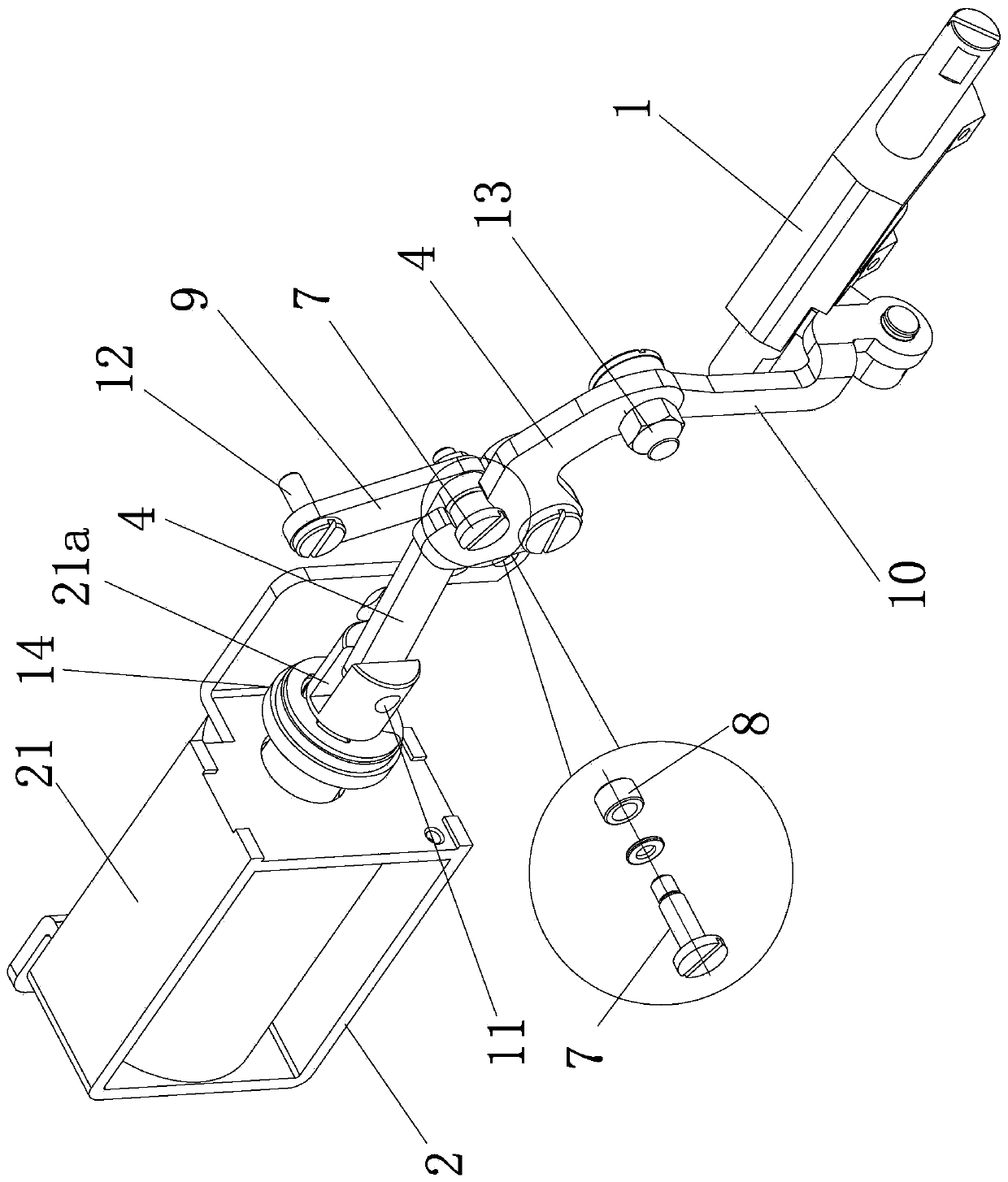
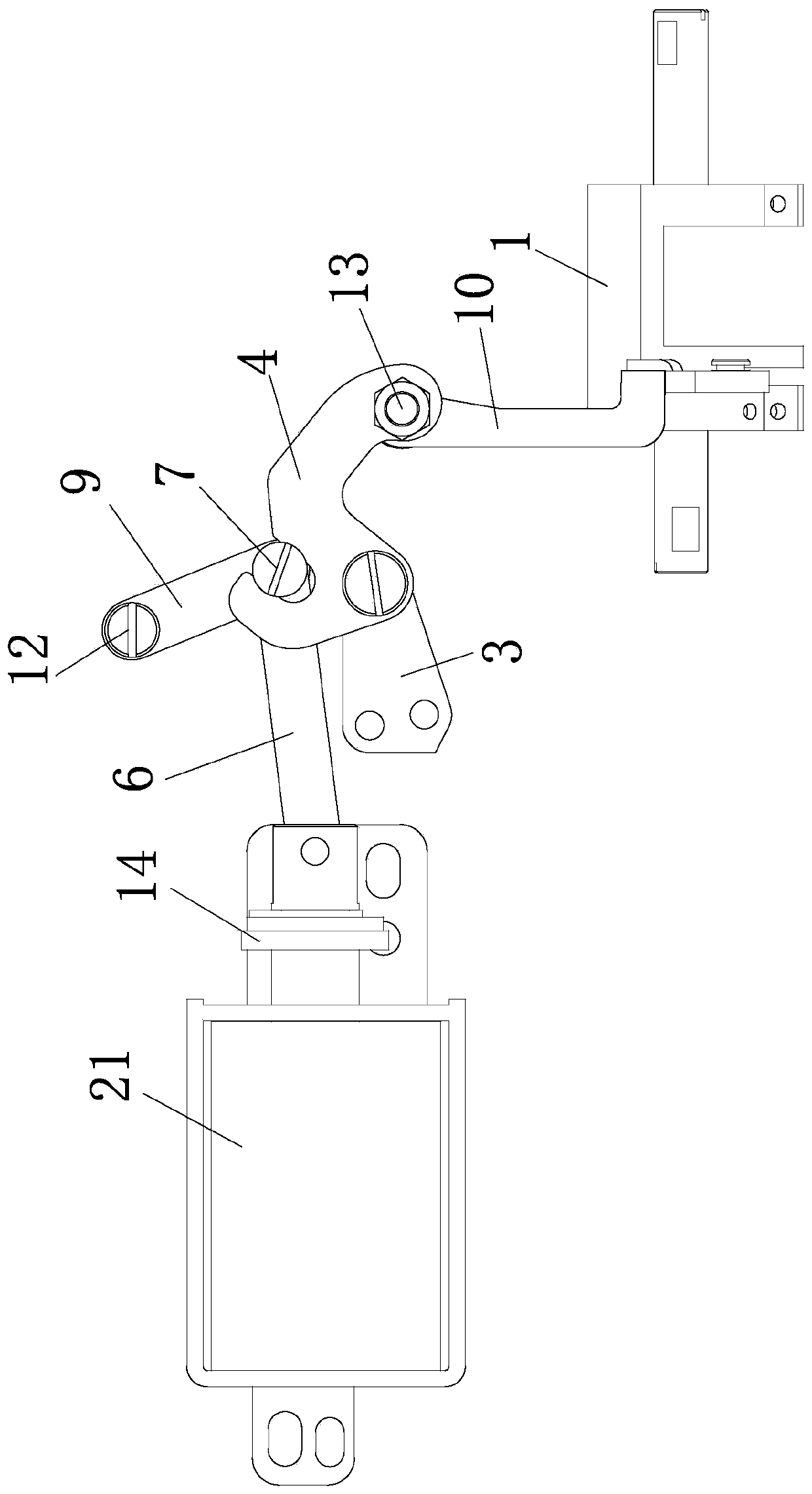
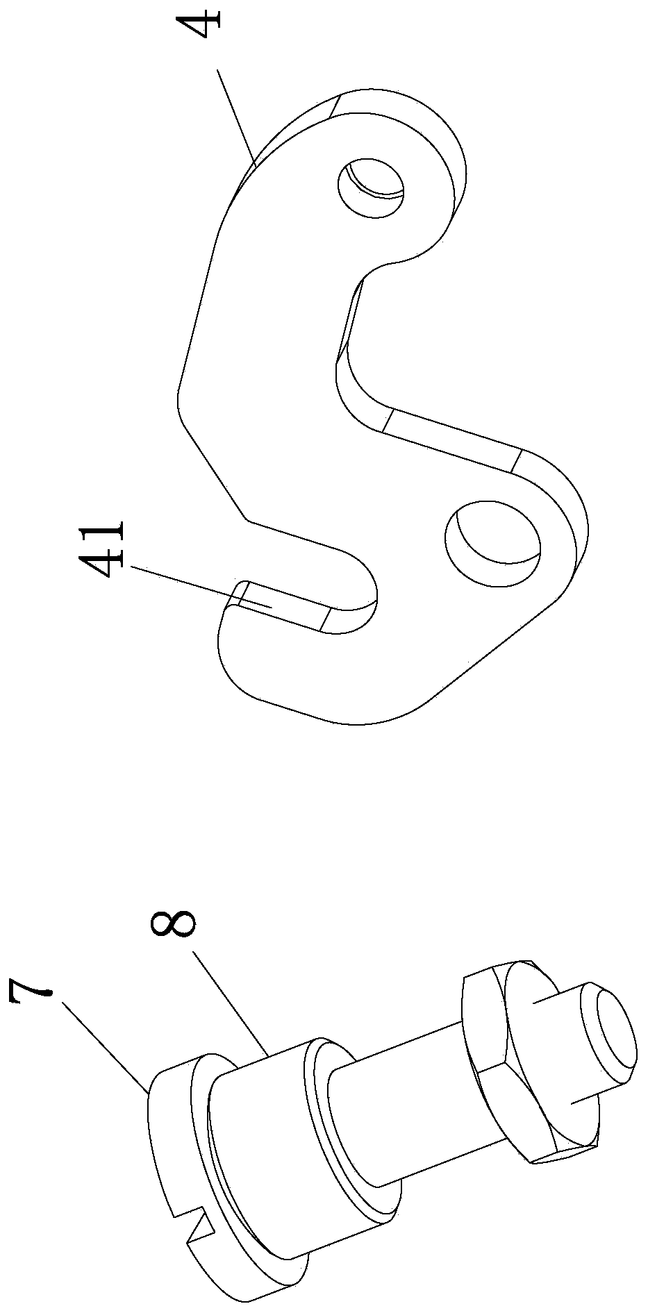
[0025] Such as Figure 1 to Figure 3 As shown, the sewing machine includes a base plate, and the reverse stitching structure includes a swing seat 1, a drive member 2 fixed on the base plate, and a crank support 3. The positioning pin 5 is rotatably connected to the crank support 3, the output shaft of the driver 2 is connected to the crank rod 6, the end of the crank rod 6 is connected to the rolling screw 7, and the rolling screw 7 is connected to the auxiliary rod 9, the auxiliary rod One end of 9 is hinged on the base plate; one end of backstitch crank 4 has a chute 41, and one end of rolling screw 7 is movably engaged in chute 41; the swing seat 1 is connected with a swing pull rod 10 that can drive it to swing, and t...


PUM


Abstract

The invention provides a backstitch structure of a sewing machine, and belongs to the technical field of clothing manufacturing devices. The technical problem that a backstitch structure of an existing sewing machine cannot save labor enough is solved. The sewing machine comprises a bottom plate. The backstitch structure comprises a swing base, a driving piece fixedly arranged on the bottom plate,and a crank support. A backstitch crank is arranged on the crank support and rotationally connected to the crank support through a crank axial pin. An output shaft of the driving piece is connected with a crank pull rod. One end of the crank pull rod is connected with a rolling screw. The rolling screw is connected with an auxiliary rod. One end of the auxiliary rod is hinged to the bottom plate.A slide groove is formed in one end of the backstitch crank. One end of the rolling screw is movably clamped in the slide groove. A swing pull rod which can drive the swing base to swing is connectedto the swing base. One end of the swing pull rod is connected with the other end of the backstitch crank. According to the backstitch structure, by adding the auxiliary rod and reasonably arranging the connecting positions of all the parts, the torque transmission efficiency of a backstitch transmission structure is improved.

Description

technical field [0001] The invention belongs to the technical field of sewing machines, and relates to a reverse sewing structure of a sewing machine. Background technique [0002] A sewing machine is a machine that uses one or more sewing threads to form one or more stitches on the sewing material to interweave or sew one or more layers of sewing material. The sewing machine can sew fabrics such as cotton, fiber crops, silk, wool, and artificial fibers, and products such as leather, plastics, and paper. The existing sewing machine usually also has a reverse stitching structure. The reverse stitching mechanism on the sewing machine generally includes two types. One is to manually drive the reverse stitching mechanism through the reverse stitching wrench to realize the reverse stitching, and the other is to use the electromagnet Drive the action of reverse sewing mechanism to realize reverse sewing. For example, the authorized announcement number is CN204959246U, which disc...

Claims


Application Information

Patent Timeline
Patent Type & Authority Applications(China)
IPC IPC(8): D05B69/16
Inventor 柯祥林祝书伟郑吉张友友
Owner JACK SEWING MASCH CO LTD
Learn More