
Prefabricated assembly pier and beam fixing structure and construction method thereof

A prefabricated assembly and prefabricated structure technology, applied in the erection/assembly of bridges, bridges, bridge parts, etc., can solve the problem of large bending moment at the bottom of the pier, the bending resistance of the top of the pier is not used, and the dead weight of the cover beam exceeds the local transportation and lifting capacity, etc. problems, to achieve the effect of reducing weight and reducing the amount of engineering

Pending Publication Date: 2019-06-11
SHANGHAI URBAN CONSTR DESIGN RES INST GRP CO LTD
View PDF0 Cites 1 Cited by
  • Summary
  • Abstract
  • Description
  • Claims
  • Application Information

AI Technical Summary

Problems solved by technology

[0004] The structural system has the following problems: under the load along the bridge direction, the pier column is equivalent to a cantilever beam fixed at one end, resulting in no use of the bending capacity of the pier top and a large bending moment at the bottom of the pier; for cities with six lanes with a wide bridge deck For viaducts, the overall prefabricated cover girder often causes the self-weight of the cover beam to exceed the local transportation and lifting capacity, so it has to be spliced ​​in horizontal segments; the supports are prone to various diseases and require regular maintenance and smoother

Method used


Image

  • Prefabricated assembly pier and beam fixing structure and construction method thereof
  • Prefabricated assembly pier and beam fixing structure and construction method thereof
  • Prefabricated assembly pier and beam fixing structure and construction method thereof

Examples


Embodiment

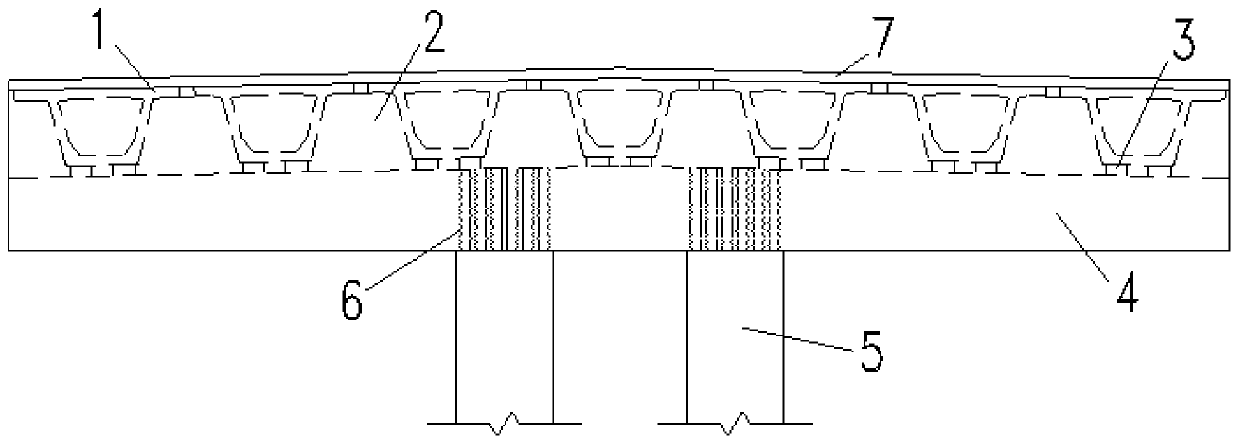
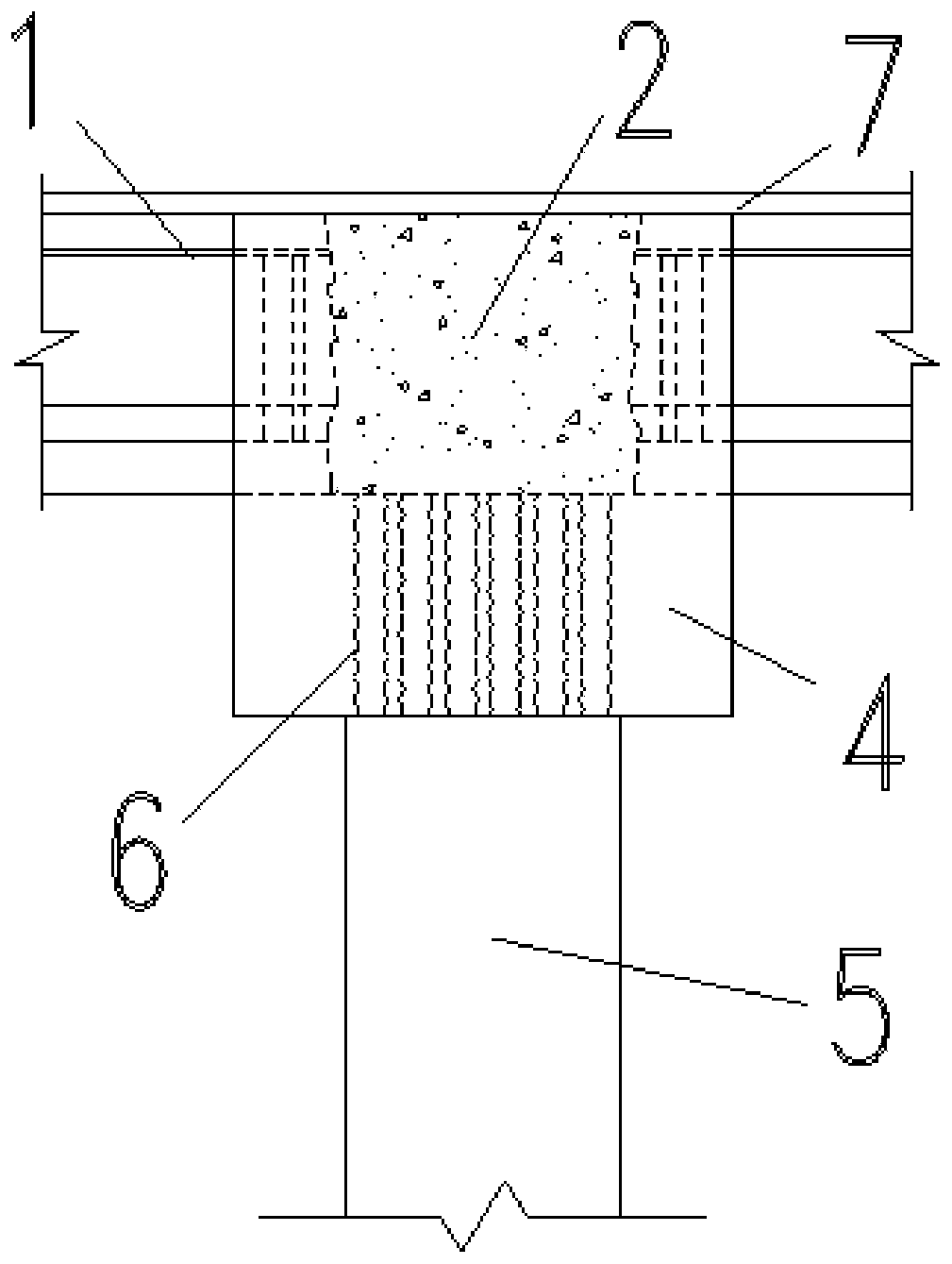
[0037] Such as Figure 1 to Figure 3 As shown, the prefabricated assembled pier beam consolidation structure includes a main beam 1 and a prefabricated pier column 5, and a cover beam is provided between the main beam 1 and the prefabricated pier column 5.

[0038] Among them, the cover beam includes the upper cast-in-place structure 2 and the lower prefabricated structure 4;

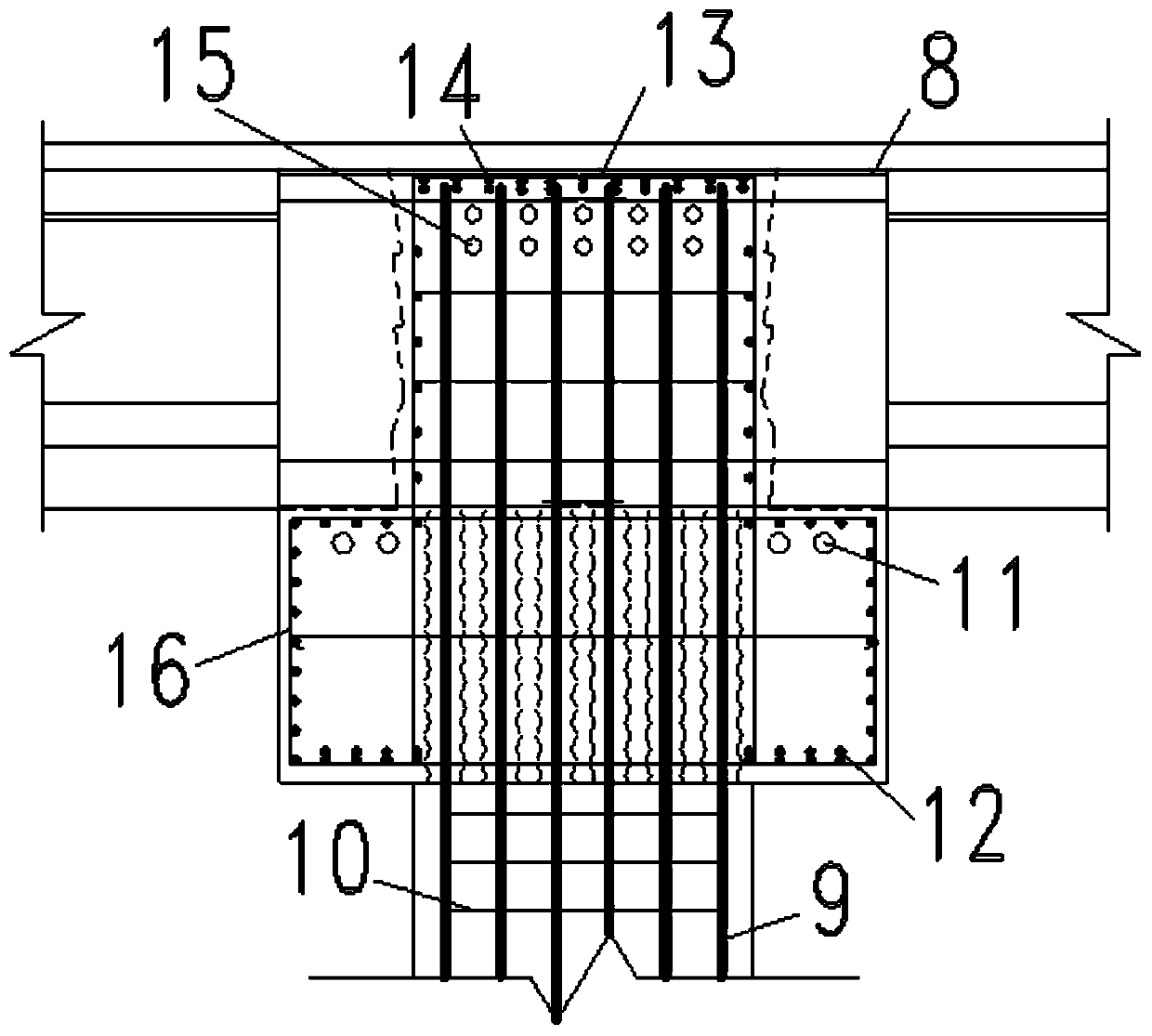
[0039] The upper cast-in-place structure 2 is provided with several welded steel bars 13 along the length direction;

[0040] The two ends of several welded steel bars 13 are respectively connected with the corresponding main beam longitudinal main bars 8 of the two main beams 1 located on both sides of the cover beam;

[0041] The lower prefabricated structure 4 is provided with a plurality of metal bellows 6 parallel to each other and arranged vertically corresponding to the positions connected to each prefabricated pier column 5;

[0042] Each prefabricated pier column 5 includes several pier colum...


PUM


Abstract

The invention discloses a prefabricated assembly pier and beam fixing structure and a construction method thereof. The prefabricated assembly pier and beam fixing structure comprises girders, prefabricated pier columns and a bent cap. The bent cap comprises an upper layer cast-in-place structure and a lower layer prefabricated structure. Multiple welding reinforcing steel bars arranged on the upper layer cast-in-place structure are connected with corresponding girder longitudinal main ribs of the two girders located on the two sides of the bent cap. The position, correspondingly connected witheach prefabricated pier column, of the lower layer prefabricated structure is provided with multiple parallel vertically-arranged metal corrugated pipes. Each prefabricated pier column comprises multiple vertically-arranged pier column main ribs. The upper ends of the multiple pier column main ribs extend upwards out of the upper faces of the corresponding prefabricated pier column. The extend-out portions of the multiple pier column main ribs are matched with the multiple metal corrugated pipes. In the installation process, each pier column main rib penetrates through the corresponding metalcorrugated pipe. The bending moment load of each pier bottom in the bridge axis direction is reduced, the weight of the prefabricated bent cap is greatly reduced, and the requirements for local transportation and elevating capacity can be easily met.

Description

technical field [0001] The invention relates to the technical field of prefabricated pier beam manufacturing, in particular to a prefabricated assembled pier beam consolidation structure and a construction method thereof. Background technique [0002] With the expansion of the concept of prefabricated bridges from the superstructure to the substructure, the scope of prefabricated components has gradually covered the main bridge stress components such as main prefabricated assembled pier beam consolidation beams, cover beams, and pier columns. [0003] In the existing prefabricated bridge system, the main girder rests on the cover beam through the support, and the cover beam is consolidated with the pier column to transfer the load of the superstructure to the foundation. [0004] The structural system has the following problems: under the load along the bridge direction, the pier column is equivalent to a cantilever beam fixed at one end, resulting in no use of the bending c...

Claims


Application Information

Patent Timeline
IPC IPC(8): E01D21/00E01D19/00E01D19/02
Inventor 胡皓周良闫兴非陆元春甘露
Owner SHANGHAI URBAN CONSTR DESIGN RES INST GRP CO LTD
Learn More