Shield construction method of contact channel

A technology for connecting passages and construction methods, applied in tunnels, tunnel linings, earth-moving drilling, etc., can solve the problems of small internal space of the main tunnel, inability to assemble segments, and excessive construction time, so as to shorten construction time, save personnel and Equipment operation space, eliminating the effect of shield tail gap

Active Publication Date: 2019-06-11
SUN YAT SEN UNIV
View PDF8 Cites 12 Cited by
  • Summary
  • Abstract
  • Description
  • Claims
  • Application Information

AI Technical Summary

Problems solved by technology

However, the method of freezing the ground with the large-scale freezing method on the whole line is time-consuming and labor-intensive, and the construction period is long and the construction cost is high.
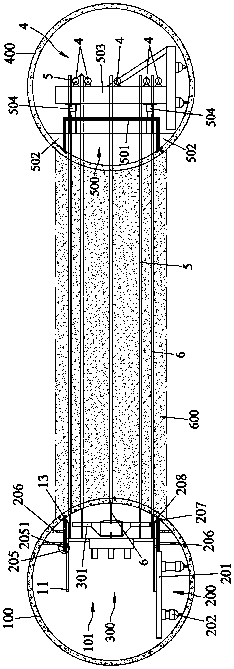
2. The internal space of the main tunnel is small, and it is difficult to dismantle the entire shield machine 300 out of the main tunnel after the shield tunneling construction of the communication channel is completed
However, it still has deficiencies. The reason is that there is a problem in all shield machine excavations at present, that is, the forward advancement of the shield and the assembly of segments are two independent processes.
When the jack support shoe of the shield machine is on the side wall of the newly assembled segment ring, it can be excavated forward, and the segment cannot be assembled at this time; when the jack support shoe of the shield machine is retracted, the segment ring can be assembled , and at this time it is impossible to dig into
The two processes are interleaved, and the shield machine frequently pauses and advances until the segment assembly of the connecting tunnel is completed, which not only requires more construction time, but also causes a large disturbance to the ground

Method used


Image

  • Shield construction method of contact channel
  • Shield construction method of contact channel
  • Shield construction method of contact channel

Examples


Embodiment Construction

[0028]The technical solutions in the embodiments of the present invention will be clearly and completely described below in conjunction with the accompanying drawings. Apparently, the described embodiments are only part of the embodiments of the present invention, not all of them. Based on the embodiments of the present invention, all other embodiments obtained by persons of ordinary skill in the art without creative efforts fall within the protection scope of the present invention.

[0029] It should be noted that if the embodiment of the present invention involves directional indications (such as up, down, left, right, front, back, top, bottom, inside, outside, vertical, horizontal, vertical, counterclockwise, clockwise, circumferential direction, radial direction, axial direction...), the directional indication is only used to explain the relative positional relationship, movement conditions, etc. When a change occurs, the directional indication changes accordingly.

[003...


PUM


Abstract

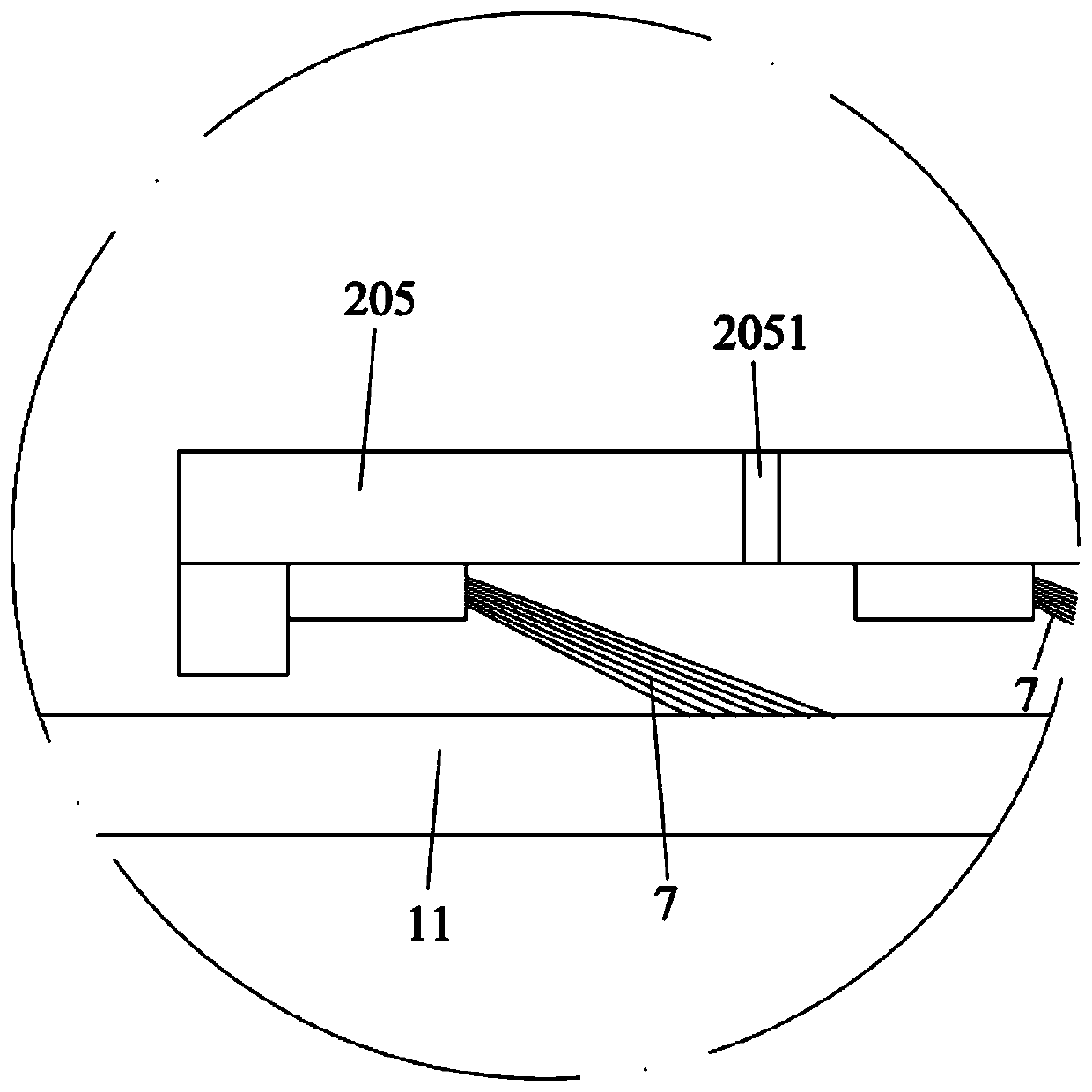
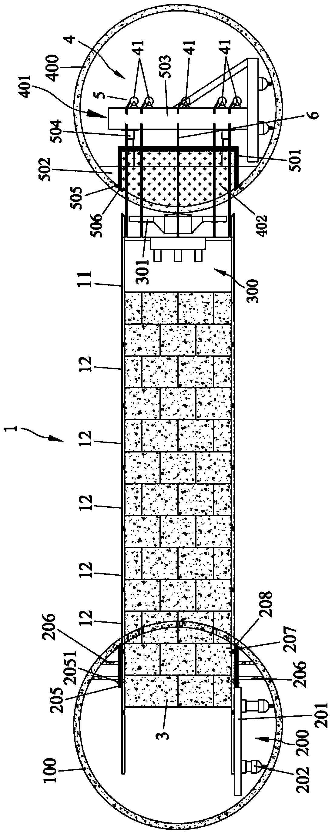
The invention discloses a shield construction method of a contact channel. A plurality of drilling holes penetrating through main tunnel segments in an originating terminal, contacting channel groundlayer and main tunnel segments in a receiving terminal are drilled through a drilling rod and arranged in the circumferential direction in the area, corresponding to the contact channel, of the originating terminal, the drilling holes are used for being penetrated by steel ropes, a hauling mechanism is arranged at the receiving terminal, the two ends of the multiple steel ropes are connected witha shield shell of a shield tunneling machine in the originating terminal and the hauling mechanism in the receiving terminal, thus the hauling mechanism can pulling the shield tunneling machine to head forward through the steel ropes, under the condition that the shield tunneling machine is not paused to tunneling, segment rings and prolonged shield shells are sequentially assembled until the tunneling construction of the contact channel is completed, and an extended type shield shell and a contact channel segment ring extending from the originating terminal to the receiving terminal are formed. Construction time can be greatly shortened, the construction efficiency is improved, the construction cost is lowered, disturbance of stratum is reduced, and constriction risks such as ground surface settlement and excavation ground surface collapse are prevented.

Description

technical field [0001] The invention relates to the technical field of communication passages, in particular to a shield construction method for communication passages. Background technique [0002] The connecting channel is set between two main tunnels (such as subway tunnels, highway tunnels, pipe galleries, or deep-buried drainage tunnels, etc.) and connects the two main tunnels. About meters, it plays the role of communication, drainage, maintenance and fire rescue. Taking subway tunnels or highway tunnels as an example, if there is a problem with one main tunnel as a whole, pedestrians can be transferred to another main tunnel through the connecting passage, thereby greatly increasing the safety factor of pedestrians. At the same time, it is also convenient that when an accident occurs in one main tunnel, rescuers can reach the communication passage from another main tunnel, and then enter the place where rescue is needed (the main tunnel where the accident occurred) t...

Claims


Application Information

Patent Timeline
Patent Type & Authority Applications(China)
IPC IPC(8): E21D9/06E21D11/08E21D11/10
Inventor 梁禹黄林冲马建军赖正首
Owner SUN YAT SEN UNIV
Why Eureka
Try Eureka