
Waste gas residual heat recycling device for organic silicon production technology

A waste heat recovery device and production process technology, applied in the direction of heat exchange equipment, heat exchanger types, heat exchanger shells, etc., can solve the problems of one-time waste gas injection waste gas leakage, accidental burns, waste of energy, etc., to achieve heat recovery The effect of high utilization rate, increased residence time, and improved utilization rate

Inactive Publication Date: 2019-06-11
李凤英
View PDF0 Cites 1 Cited by
  • Summary
  • Abstract
  • Description
  • Claims
  • Application Information

AI Technical Summary

Problems solved by technology

[0003] However, the existing waste gas and waste heat recovery devices used in the silicone production process still have certain defects when they are in use. When the high-temperature waste gas is injected into the device during recovery, too much waste gas will often be injected at the same time, resulting in part of the waste gas. Not only will it easily cause accidental burns but also waste a lot of energy

Method used


Image

  • Waste gas residual heat recycling device for organic silicon production technology
  • Waste gas residual heat recycling device for organic silicon production technology
  • Waste gas residual heat recycling device for organic silicon production technology

Examples


Embodiment Construction

[0017] The following will clearly and completely describe the technical solutions in the embodiments of the present invention with reference to the accompanying drawings in the embodiments of the present invention. Obviously, the described embodiments are only some, not all, embodiments of the present invention. Based on the embodiments of the present invention, all other embodiments obtained by persons of ordinary skill in the art without making creative efforts belong to the protection scope of the present invention.

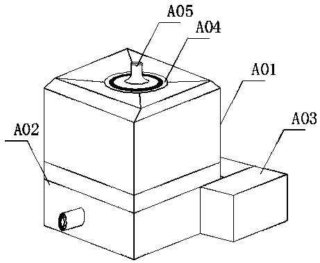
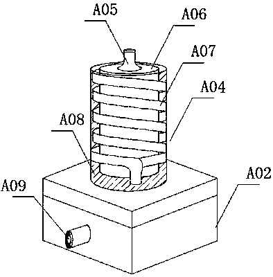
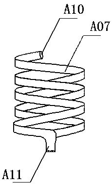
[0018] see Figure 1-4 As shown, a device for recovering waste heat from waste gas in the silicone production process, including an incubator A01, a gathering box A02 and a fixing frame A03, an air intake pipe A09 is installed on the side wall of the gathering box A02, and the back side of the gathering box A02 is clamped and fixed Frame A03, heat preservation box A01 with a sealed structure is installed on the top of the gathering box A02, the outer chimney A...


PUM


Abstract

The invention discloses a waste gas residual heat recycling device for an organic silicon production technology. The waste gas residual heat recycling device comprises a heat insulation box, a gathering box, a fixed frame, an outer chimney, a gas leakage pipe, an inner chimney, a spiral pipe, a water collector, a gas inlet pipe, a butt joint opening, a collection opening, short bulges, gaps and long bulges. The waste gas residual heat recycling device disclosed by the invention has the beneficial effects that the plurality of short bulges and long bulges are arranged on an inner wall of the inner chimney; the long and short bulges are symmetrically arranged; the gap with a Z-shaped structure is formed by each two groups of the long and short bulges; and waste gas passes through the gaps with the Z-shaped structure in a circulation process so that the retention time is prolonged. The spiral pipe matched with the distance between the inner wall of the outer chimney and an outer wall of the inner chimney is arranged between the inner wall of the outer chimney and the outer wall of the inner chimney; the spiral pipe is wound on the outer wall of the inner chimney and the butt joint opening of the spiral pipe is communicated with the gas leakage pipe; when excessive gas enters in one step, the gas is leaked; and meanwhile, the leaked gas is directly guided into the collection opening of the spiral pipe and the heat of the waste gas guided into the spiral pipe also can be recycled.

Description

technical field [0001] The invention relates to a waste gas waste heat recovery device, in particular to a waste gas waste heat recovery device used in the organic silicon production process, and belongs to the field of waste gas treatment. Background technique [0002] Organosilicon often undergoes a series of treatment steps during processing. Since organosilicon requires high-temperature heat treatment, a large amount of high-temperature exhaust gas is often generated during the heat treatment process. For these high-temperature exhaust gases, waste heat recovery devices are often used to recover the heat. The recovered heat can be used for secondary use in the silicone production process, thereby increasing the utilization rate of energy and saving costs. [0003] However, the existing waste gas and waste heat recovery devices used in the silicone production process still have certain defects when they are in use. When the high-temperature waste gas is injected into the ...

Claims


Application Information

Patent Timeline
Patent Type & Authority Applications(China)
IPC IPC(8): F28D7/02F28D21/00F28F9/22
Inventor 不公告发明人
Owner 李凤英
Learn More