A polarized light intensity shaping device

A shaping device and polarized light technology, applied in optics, optical components, instruments, etc., can solve the problems of serious energy loss and difficult processing of aspheric lenses, and achieve the effects of easy processing, smooth and uniform spatial distribution, and convenient use

Active Publication Date: 2020-12-15
TECHNICAL INST OF PHYSICS & CHEMISTRY - CHINESE ACAD OF SCI
View PDF5 Cites 0 Cited by
  • Summary
  • Abstract
  • Description
  • Claims
  • Application Information

AI Technical Summary

Problems solved by technology

[0003] The method that people often used in the early days was to expand the laser beam first, and then pass the expanded beam through the diaphragm. The diaphragm only allows the part of the beam with a relatively uniform light intensity distribution to pass through, so that a uniformly distributed light intensity can be obtained. Although this method is simple, the energy loss is very serious
In order to obtain a suitable conversion, an anti-Gaussian distribution absorption filter can also be used. This filter is a plano-convex lens made of absorbing glass, but this lens can only obtain a uniform beam with a utilization efficiency of 37%.
In addition, Gaussian beam shaping can also be achieved by using an aspheric lens system, but the aspheric lens in this system is difficult to process

Method used


Image

  • A polarized light intensity shaping device
  • A polarized light intensity shaping device
  • A polarized light intensity shaping device

Examples


Embodiment Construction

[0028] In order to make the object, technical solution and advantages of the present invention clearer, the present invention will be further described in detail below in combination with specific embodiments and with reference to the accompanying drawings. It should be understood that these descriptions are exemplary only, and are not intended to limit the scope of the present invention. Also, in the following description, descriptions of well-known structures and techniques are omitted to avoid unnecessarily obscuring the concept of the present invention.

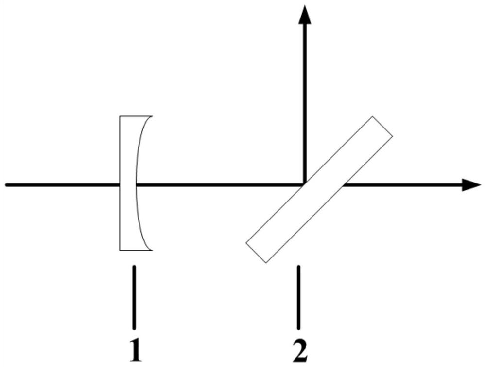
[0029] figure 1 is a schematic structural diagram of the polarized light intensity shaping device according to the first embodiment of the present invention.

[0030] Such as figure 1 As shown, the polarized light intensity shaping device includes: a spherical optically active crystal 1 and a polarizer 2 sequentially arranged along the optical axis of the polarized light.

[0031] In the spherical optically active crys...


PUM

PropertyMeasurementUnit
wavelengthaaaaaaaaaa

Abstract

The invention discloses a polarized light intensity shaping device. The device comprises a spherical gyrotropic crystal and a polarizer which are sequentially arranged along an optical axis of polarized light, wherein at least one of two faces which are opposite along the direction of the optical axis of the spherical gyrotropic crystal is a spherical surface, and the sphere center of the spherical surface is arranged on the optical axis; the thickness of the spherical gyrotropic crystal is a preset thickness in order to change a rotating angle in a polarization direction of the polarized light penetrating the spherical gyrotropic crystal; the polarizer is arranged according to a Brewster angle, and the light input into the surface of the polarizer forms a beam of P polarized light with the uniform intensity and a beam of S polarized light with the uniform intensity. At least one face of the spherical gyrotropic crystal in the polarized light intensity shaping device is the spherical surface, through the arrangement of the preset thickness, the polarized light penetrating through the spherical gyrotropic crystal is transmitted to the edge from the center of the radial light spot, and the polarization direction is rotated at different angles along with the increase of the radius of the light spot, so that the reflectivity is changed along with the change of the radius of the light spot when the polarized light passes through the polarizer, and thus the light intensity is shaped, and two polarized beams with smooth and uniform spatial distribution are obtained.

Description

technical field [0001] The invention relates to the field of light intensity shaping, in particular to a polarized light intensity shaping device. Background technique [0002] Since the advent of the first ruby ​​laser, lasers have been widely used due to their high monochromaticity and high brightness. However, in the technical fields of laser welding, laser processing, display, holography, optical storage and medicine, a beam with good uniformity is often required. If the energy distribution of the laser is uneven, the local temperature will be too high, which will destroy the material properties, thereby affecting the effect of the interaction between the laser and the material. Since the laser is generated from the multiple reflections of light in the resonator, the emitted light of the laser must satisfy a certain mode distribution. The most common transverse mode obeys Gaussian distribution and super-Gaussian distribution. The light intensity of the laser beam is gen...

Claims


Application Information

Patent Timeline
Patent Type & Authority Patents(China)
IPC IPC(8): G02B27/28G02B27/09
Inventor 薄勇宗庆霜卞奇左军卫彭钦军许祖彦
Owner TECHNICAL INST OF PHYSICS & CHEMISTRY - CHINESE ACAD OF SCI
Why Eureka
Try Eureka