Bracket with oblique marker and its application, system and method for adjusting oblique direction of bracket thereof
A technology of markers and bevels, which is applied to the adjustment of the system and the direction of the bevel of the stent. In the field of stents with beveled ends, it can solve the problem that the combination of markers cannot provide accurate and fast indication of the direction of the bevel of the stent, so as to shorten the operation time, The effect of reducing the workload and reducing the difficulty of operation
- Summary
- Abstract
- Description
- Claims
- Application Information
AI Technical Summary
Problems solved by technology
Method used
Image
Examples
Embodiment 1
[0120] For an example of a marker combination, see Figure 11A , Figure 11B , the two alignment markers are cylinders with the same thickness, wherein the bottom surface of the alignment marker 23 is circular, and the bottom surface of the alignment marker 24 is elliptical. Obviously, any diameter of the circle is Its maximum width line, and the major axis of the ellipse is its only maximum width line, the major axis of the ellipse is twice the diameter of the circle, the length of the minor axis of the ellipse is equal to the diameter of the circle and the thickness of the cylinder, and the ellipse The major axis of is parallel to a diameter of the circle and the ZZ axis two by two. see Figure 12 , when the angle between the projection direction of the ray and the line between the two alignment markers changes, the plane projection images of the two alignment markers are ellipses with different long-axis directions. Since the plane projection images The general direction...
Embodiment 2
[0122] In the same way, Figure 13A , Figure 13B The two alignment markers in the illustrated embodiment are also cylinders, wherein the bottom surface of the alignment marker 23 is circular, while the bottom surface of the alignment marker 24 is figure-eight, and the bottom surface of the figure-eight has and only has one maximum width The line is parallel to the ZZ axis and is twice the circular diameter of the bottom surface of the alignment marker 23 . according to Figure 14 The planar projection image A of the alignment marker can also be used to quickly identify and distinguish two alignment markers by using the length difference along the ZZ axis of the planar projection image of the alignment marker.
Embodiment 3
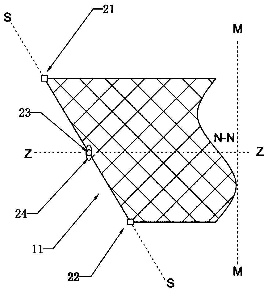
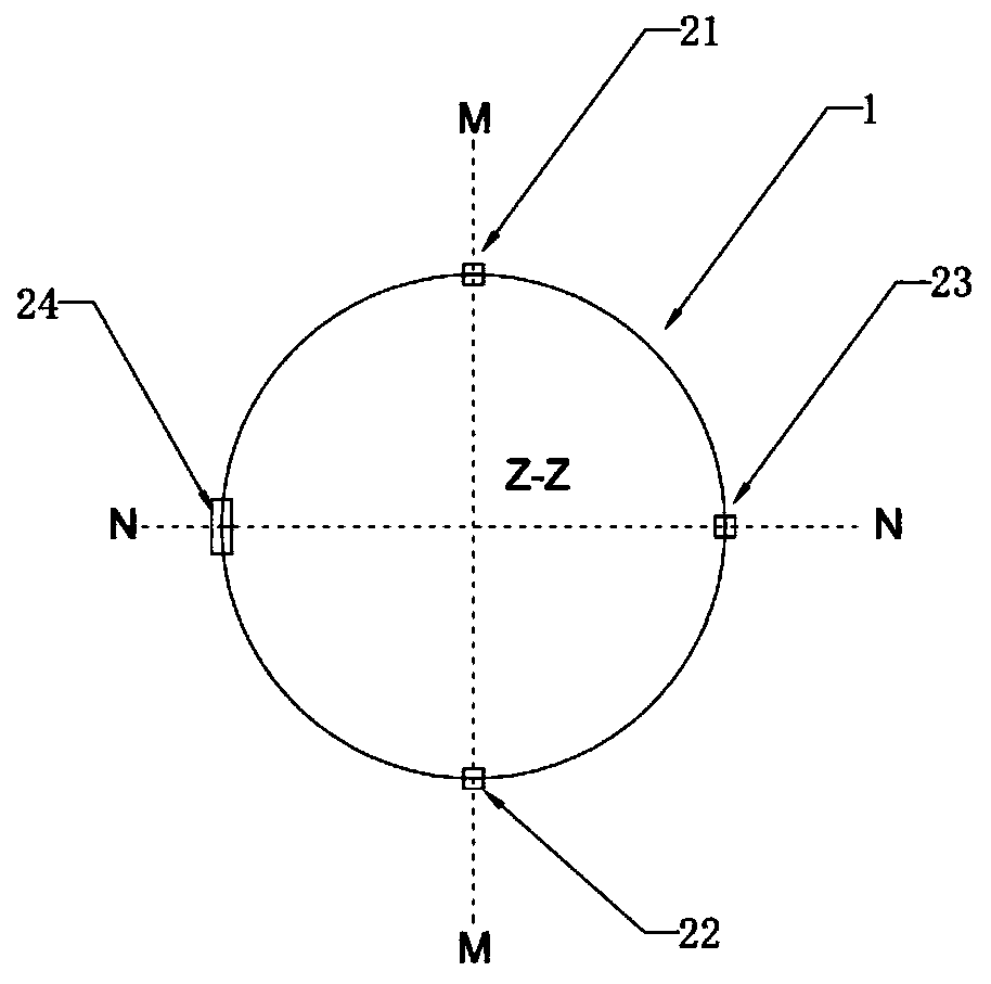
[0124] see Figure 2A , Figure 2B , which with Figure 11A The embodiment is different in that the major axis of the oval bottom surface of the alignment marker 24 is perpendicular to the ZZ axis. see Figure 4 , Figure 5 , Figure 6 and Figure 7 , shows the plane projection diagram A where the included angles between the ray projection direction and the line connecting the two alignment markers are 0 degrees, 30 degrees, 45 degrees and 80 degrees. By comparing the lengths of the projection images of the two alignment markers along the MM axis, it is possible to quickly distinguish the P1 enantioposition marker 24 . In addition, it can be seen from the figure that as the included angle increases, the lengths of the projection images of the two alignment markers along the MM axis gradually approach. In order to ensure that the comparison and distinction of the maximum width of the planar projection images of the two alignment markers can be achieved within a small ran...
PUM
 Abstract
Description
Claims
Application Information
 - R&D
- Intellectual Property
- Life Sciences
- Materials
- Tech Scout
- Unparalleled Data Quality
- Higher Quality Content
- 60% Fewer Hallucinations
Browse by: Latest US Patents, China's latest patents, Technical Efficacy Thesaurus, Application Domain, Technology Topic, Popular Technical Reports.
© 2025 PatSnap. All rights reserved.Legal|Privacy policy|Modern Slavery Act Transparency Statement|Sitemap|About US| Contact US: help@patsnap.com


