[0016] All the features disclosed in this specification, or all disclosed methods or steps in the process, except for mutually exclusive features and/or steps, can be combined in any manner.
[0017] Any feature disclosed in this specification (including any appended claims, abstract and drawings), unless specifically stated, can be replaced by other equivalent or equivalent alternative features. That is, unless otherwise stated, each feature is just one example of a series of equivalent or similar features.
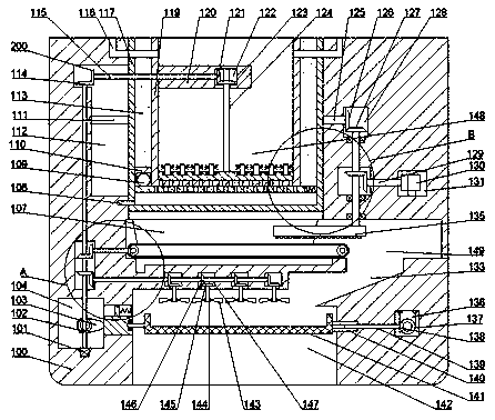
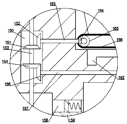
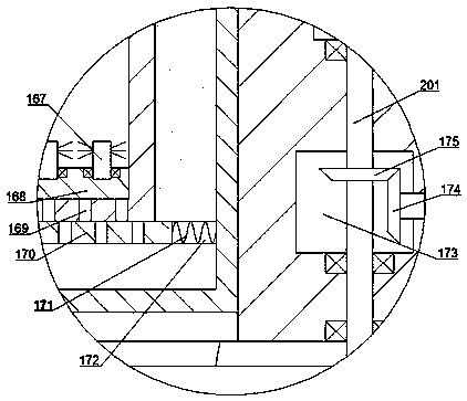
[0018] The following will be combined with the appendix in the embodiment of the present invention Figure 1 to Figure 3 The technical solutions in the embodiments of the present invention are described clearly and completely. Obviously, the described embodiments are only a part of the embodiments of the present invention, rather than all the embodiments. Based on the embodiments of the present invention, all other embodiments obtained by those of ordinary skill in the art without creative work shall fall within the protection scope of the present invention. Such as Figure 1 to Figure 3 As shown, an ultrasonic cleaning machine of the present invention, wherein the ultrasonic cleaning machine includes a main body 100, the top end of the main body 100 is provided with a top cavity 112, and the back wall of the top cavity 112 is fixed An ultrasonic cleaning mechanism is provided. The top cavity 112 is provided with a cleaning box mechanism. The main body 100 at the bottom of the top cavity 112 is provided with a spray cleaning chamber 149, and the spray cleaning chamber 149 is provided with a spray chamber. The main body 100 at the top of the spray washing cavity 149 is provided with a spray bottom cavity 173, and the main body 100 at the top of the spray bottom cavity 173 is provided with a right cavity 128. The main body 100 on the right side of the spray-washing bottom cavity 173 is provided with a winding wheel cavity 131, and the main body 100 at the bottom of the spray-washing chamber 149 is provided with a drying chamber 142, the drying chamber 142 and The spraying chambers 149 are connected by a ramp channel 133, the ramp channel 133 is arranged obliquely, the drying chamber 142 is provided with a drying mechanism, and the main body on the right side of the drying chamber 142 A bottom winding cavity 136 is opened in 100, a power cavity 104 is opened in the main body 100 on the left side of the drying cavity 142, and a bevel gear transmission cavity is opened in the main body 100 on the top of the power cavity 104 150, the power cavity 104 and the bevel gear transmission cavity 150 are rotatably provided with a motor power shaft 153 extending up and down. The bottom extension of the motor power shaft 153 extends into the power cavity 104 and its end is connected to The power motor 101 fixedly embedded in the bottom wall of the power cavity 104 is power connected, the back wall of the power cavity 104 is rotated with a cam 103, which is located on the outer wall of the motor power shaft 153 in the power cavity 104 The power cavity bevel teeth 102 meshing with the cam 103 are fixed in the circumferential direction, the top extension of the motor power shaft 153 extends into the top cavity 112, and the end of the power shaft top teeth 114 is fixed, located The outer wall of the motor power shaft 153 in the bevel gear transmission cavity 150 is provided with fan power bevel teeth 154 in the circumferential direction, and the outer wall of the motor power shaft 153 at the top of the fan power bevel teeth 154 is fixed in the circumferential direction. There are belt-powered bevel teeth 151, and the belt-powered bevel teeth 151 are located in the bevel gear transmission cavity 150.
[0019] Beneficially, the cleaning box mechanism includes a turning box 117 rotatably installed in the cleaning cavity 148, a left turning shaft 111 is fixedly fixed on the left end surface of the turning box 117, and the left turning shaft 111 The left end of the top cavity 112 is rotationally matched with the left end wall of the top cavity 112, the right end of the flip box 117 is fixedly provided with a right flip shaft 125, and the right end of the right flip shaft 125 extends Is inserted into the right cavity 128 and is fixedly provided with a turning shaft bevel tooth 126 at its end. The right turning shaft 125 is rotationally matched with the left end wall of the right cavity 128, and the turning box 117 A cleaning box 119 is fixedly provided, a heating net 113 is provided between the cleaning box 119 and the turning box 117, a baffle fixing block 110 is fixed on the left end surface of the cleaning box 119, and the baffle is fixed A baffle gear 109 is provided for rotation in the block 110, a cleaning cavity 148 is opened in the cleaning box 119, the top of the cleaning cavity 148 is provided with an opening, and a support plate 120 is fixed on the left end wall of the cleaning cavity 148 , The support plate 120 is provided with a support plate cavity 122, the left end wall of the support plate cavity 122 is rotatably provided with a transverse shaft 115 extending to the left, and the right end of the transverse shaft 115 is fixedly arranged at The lateral shaft right tooth 121 in the support plate cavity 122, the left end of the lateral shaft 115 is fixedly provided with a lateral shaft left tooth 200 that is engaged with the power shaft top tooth 114, and the support plate cavity 122 The inner rotation is provided with a vertical rotation shaft 124 extending up and down. The outer wall of the vertical rotation shaft 124 is fixedly provided with a vertical rotation shaft bevel tooth 123 meshing with the horizontal rotation shaft right tooth 121. The vertical rotation shaft The extended end of the bottom of 124 is fixedly provided with a cleaning pan 168 located in the cleaning cavity 148, the top of the cleaning pan 168 rotates with a cleaning brush 167, the bottom wall of the cleaning box 119 is provided with a fine through hole 169, so The bottom end of the cleaning box 119 is provided with a baffle cavity 172, and a baffle 170 is slidably provided in the baffle cavity 172. The right end surface of the baffle 170 is different from the right end wall of the baffle cavity 172. A spring 171 is elastically connected between the main body 100 and a water inlet 116 is formed symmetrically at the top of the main body 100, and the water inlet 116 is communicated with the cleaning cavity 148.
[0020] Beneficially, the spray washing mechanism includes a pulley 165 rotatably arranged in the spray washing chamber 149. The pulleys 165 are arranged symmetrically, and the symmetrical pulleys 165 are dynamically connected by a transmission belt 166. The spray washing chamber 149 is connected to the top cavity 112, and a guide plate 107 is fixed in the spray washing chamber 149. The guide plate 107 can guide parts into the top end of the transmission belt 166. The bevel gear transmission chamber There is a belt transmission shaft 163 extending left and right to rotate between 150 and the spraying chamber 149. The right end of the belt transmission shaft 163 is fixedly provided with a belt transmission shaft engaged with the pulley 165 on the left. Right tooth 164, the left side extension of the belt transmission shaft 163 extends into the bevel gear transmission cavity 150, and the end is fixedly provided with a belt rotation shaft left tooth 152 meshing with the belt power bevel tooth 151. A bottom water removal port 162 is opened on the bottom wall of the spray washing cavity 149 near the left side, and a spray washing rotating shaft 201 extending up and down is arranged to rotate between the right cavity 128 and the spray washing cavity 149. The top extension of the spraying shaft 201 extends into the right cavity 128, and the end of the spraying shaft 201 is fixedly provided with a spraying shaft top tooth 127 meshing with the turning shaft bevel tooth 126, which is located in the spraying bottom cavity 173 A spool power tooth 175 is fixed circumferentially on the outer wall of the spraying rotating shaft 201, and a winding rotating shaft 129 extending left and right is arranged to rotate between the spraying bottom cavity 173 and the reel cavity 131 , The left end of the winding shaft 129 is fixedly provided with winding shaft bevel teeth 174 that are engaged with the winding shaft power teeth 175, and the right end of the winding shaft 129 is fixedly provided at the winding shaft In the top winding wheel 130 in the wheel cavity 131, the bottom extension of the spray washing rotating shaft 201 extends into the spray washing chamber 149, and a rotating plate 135 is fixed at its end. The bottom end of the rotating plate 135 is provided with Evenly distributed shower heads.
[0021] Beneficially, the drying mechanism includes a fan power chamber 147 opened in the top wall of the drying chamber 142, four groups of fan power chambers 147 are evenly distributed around the left and right sides, and the fan power chamber 147 is rotatably provided with A fan power shaft 157 extending left and right. The left side extension of the fan power shaft 157 extends into the bevel gear transmission cavity 150, and the end of the fan power shaft 157 is fixedly provided with a fan power shaft meshing with the fan power bevel teeth 154 On the left side tooth 156, the outer wall of the fan power shaft 157 located in the fan power chamber 147 is provided with fan power shaft bevel teeth 146 in the circumferential direction, and the bottom wall of the fan power chamber 147 is provided with rotation The fan driven shaft 144 is extended up and down. The top end of the fan driven shaft 144 is fixedly provided with a driven shaft bevel tooth 145 that is engaged with the fan power shaft bevel tooth 146. The fan driven shaft 144 The bottom end is fixedly provided with a fan 143 located in the drying chamber 142, and a sliding cavity 158 is opened on the right end wall of the power chamber 104. The drying chamber 142 is in communication, a sliding block 159 is slidably arranged in the sliding cavity 158, a spring reset mechanism is fixedly arranged at the top of the sliding block 159, the sliding block 159 and the cam 103 are pressed and slidingly fitted. A bottom reel 137 is rotatably provided on the back wall of the bottom winding cavity 136. The bottom reel 137 and the top reel 130 are connected by a winding power. The front side of the bottom reel 137 The end surface is a bevel gear design, the rear side of the bottom winding wheel 137 is powered by a small motor (not shown), and the left end wall of the bottom winding cavity 136 is rotated with a spline extending to the left. Shaft 139, the right end of the spline shaft 139 is fixedly provided with spline shaft bevel teeth 138 that are engaged with the bottom winding wheel 137, and the drying chamber 142 is provided with the bottom of the fan 143 The screen 141, the left end of the screen 141 is rotatably matched with the right end of the slider 159, and the right end of the screen 141 is fixedly provided with a spline-fitting connection with the spline shaft 139 Spline sleeve 140.
[0022] Below, the applicant will refer to the attached Figure 1-3 And the introduction of an ultrasonic cleaning machine described above. First, in the initial state, the opening of the cleaning cavity 148 faces upwards, and the baffle 170 is located on the left side of the baffle cavity 172 to the greatest extent, so that the baffle 170 will pass through. The hole 169 is shielded to ensure that no water leaks at the bottom of the cleaning chamber 148, and the rotating plate 135 is located between the turning box 117 and the transmission belt 166, and the opening of the screen 141 faces upward;
[0023] When this equipment is in use, first put the parts into the cleaning cavity 148, and pass hot water into the cleaning cavity 148 through the water inlet 116 on the left. After soaking for a period of time, start the power motor 101 to make the motor power shaft 153 Rotation in turn causes the top tooth 114 of the power shaft to rotate, so that the left side tooth 200 of the horizontal shaft drives the rotation of the horizontal shaft 115, and the right tooth 121 of the horizontal shaft drives the vertical shaft 124 to rotate, thereby rotating the sliding cavity 158, which can make the cleaning brush 167 scrubs the parts to remove the oil from the parts. After a period of time, the baffle gear 109 is activated to move the baffle 170 to the right, so that the fine through hole 169 is communicated with the fine hole on the baffle 170, and the water Out of the cleaning cavity 148, the water flows out of the device through the water outlet 108, resets the baffle 170 after it flows out, and then passes cold water into the cleaning cavity 148 through the water inlet 116 on the right to start the ultrasonic cleaning on the back wall of the top cavity 112 After a period of time, the motor on the rear side of the bottom winding wheel 137 is activated to rotate the bottom winding wheel 137 and then the top winding wheel 130, so that the winding shaft 129 rotates, and the spray washing shaft 201 rotates. The washing shaft 201 drives the right turning shaft 125 to rotate, thereby turning the turning box 117, so that the opening of the cleaning chamber 148 faces downwards, while the rotating plate 135 is turned to the right, so that the parts in the cleaning chamber 148 can fall into the transmission The top of the belt 166, at the same time, after the drop is completed, the bottom winding wheel 137 is reset to reset the turning box 117, and the rotating plate 135 is reset to start washing the parts on the transmission belt 166. At this time, the power motor 101 is turned on to make The motor power shaft 153 rotates, so that the belt power bevel gear 151 drives the left tooth 152 of the belt rotation shaft to rotate, and then the belt transmission shaft 163 drives the pulley 165 to rotate, so that the transmission belt 166 transports the parts, and the parts fall through the ramp channel 133 On the screen 141, the bevel gear 102 of the power chamber rotates at this time to rotate the cam 103, so that the slider 159 reciprocates left and right, and then the screen 141 sways left and right, and the motor power shaft 153 drives the left tooth 156 of the fan power shaft. Rotation, and then the fan power shaft 157 rotates, so that the fan 143 blows the parts on the screen 141, after drying, starts the motor behind the bottom winding wheel 137 to rotate the spline shaft 139, and then the screen 141 Turn over to pour out the parts and complete the work.
[0024] The obvious beneficial effects are as follows:
[0025] The cleaning box mechanism can perform preliminary oily treatment on the parts by immersing in hot water, reducing the time of ultrasonic cleaning, and achieving the purpose of saving electricity. Then, the clean water is passed in for ultrasonic cleaning. The ultrasonic waves generate cavitation in the water, and the parts are cleaned. Cleaning
[0026] The spray-washing mechanism can transfer the parts that fall down from the turning box to the right through the transmission belt, and at the same time, the rotating plate will spray and clean them;
[0027] The drying mechanism can accelerate the drying efficiency and reduce the drying time through the shaking of the screen and the blowing of the fan;
[0028] In summary, the present invention designs an ultrasonic cleaning machine. The cleaning box mechanism of the device can perform preliminary oily treatment on parts and components through hot water soaking, reducing the ultrasonic cleaning time and achieving the purpose of power saving. The mechanism can transfer the parts that have been turned over by the turning box to the right through the transmission belt, and the rotating plate will spray and clean them to ensure the cleanliness of the parts. The drying mechanism can be shaken by the screen plus a fan. Blowing speeds up the drying efficiency and reduces the drying time. Moreover, the device has a simple transmission structure, is not prone to failure, and is easy to maintain.
[0029] Although the embodiments of the present invention have been shown and described, those of ordinary skill in the art can understand that various changes, modifications, and substitutions can be made to these embodiments without departing from the principle and spirit of the present invention. And variations, the scope of the present invention is defined by the appended claims and their equivalents.