
A hydraulic lathe for bearing processing with resistance positioning detection

A positioning detection and bearing processing technology, which is applied in metal processing equipment, metal processing machine parts, manufacturing tools, etc., can solve the problems of test result error, feed position deviation, false alarm, etc., and prolong the service life and use of the equipment The effect of life and work efficiency improvement

Active Publication Date: 2020-11-20
营口鑫和晟机械有限公司
View PDF5 Cites 0 Cited by
  • Summary
  • Abstract
  • Description
  • Claims
  • Application Information

AI Technical Summary

Problems solved by technology

[0002] Bearing ring lathes are generally automatic loading and unloading bearing ring lathes. When the workpiece is sent into the fixture of the bearing ring lathe, the bearing ring lathe will process the workpiece regardless of whether the workpiece is in the right position. It will process some defective products that are not in the correct position, so the bearing positioning will be tested before turning, but the current technical considerations are not perfect, and it has the following disadvantages: the existing bearing testing equipment is generally installed in front of the rotating shaft, and is carried out through a hydraulic cylinder. For the probe contact detection method, due to the large vibration generated when the lathe is working, the detection device will be displaced after the lathe is used for a long time, and the feeding position of the system control probe may deviate, which will cause the bearing monitoring probe to hit the tested At the same time, the iron filings from the turning of the bearing rings splash around, and the iron filings fall on the surface of the detection probe and are not removed in time. It is easy to cause the probe to calculate the thickness of the iron filings when testing the bearing end face, resulting in test failures. As a result, errors occur, and then false alarms occur, reducing the working efficiency of the lathe

Method used


Image

  • A hydraulic lathe for bearing processing with resistance positioning detection
  • A hydraulic lathe for bearing processing with resistance positioning detection
  • A hydraulic lathe for bearing processing with resistance positioning detection

Examples


Embodiment

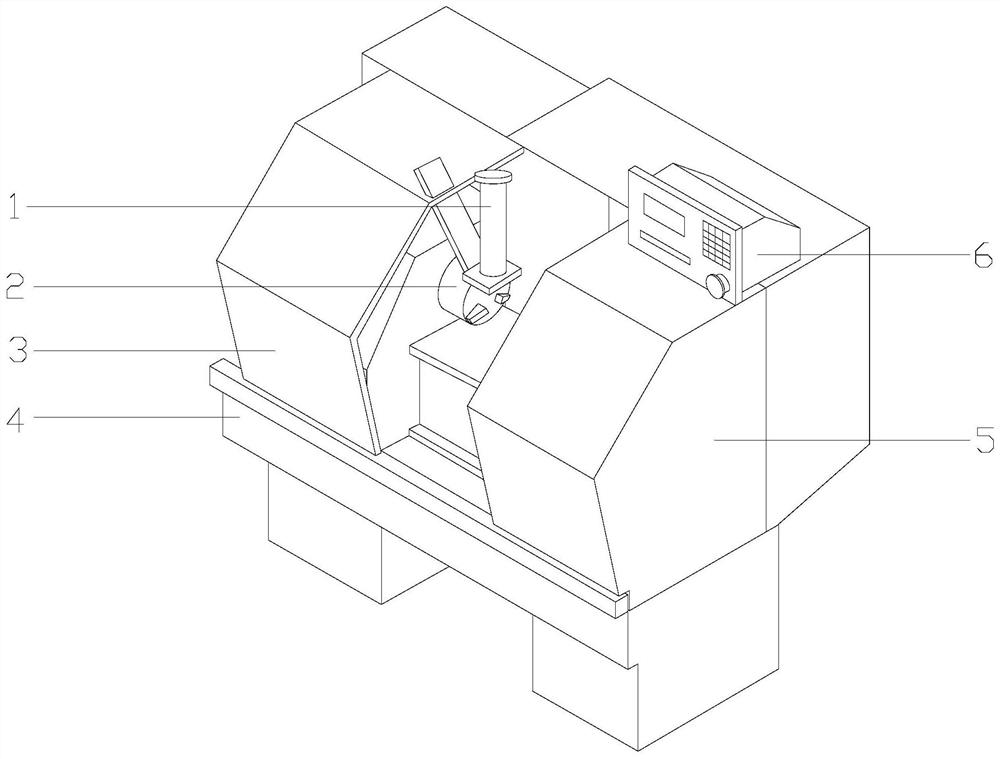
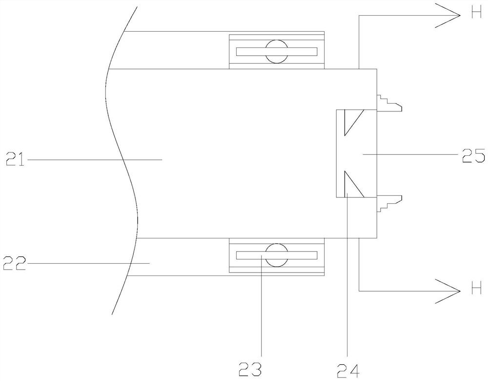
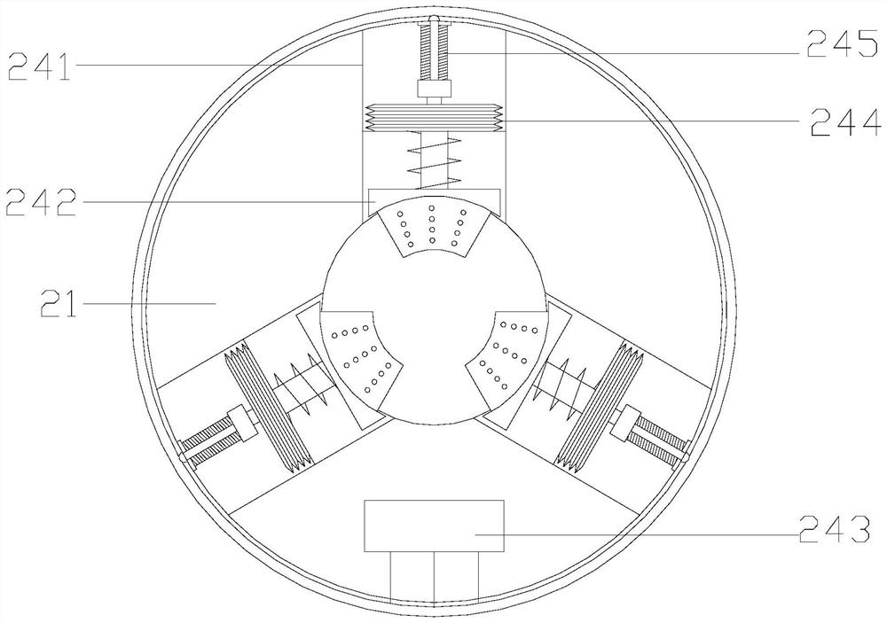
[0026] see Figure 1-Figure 2 , the present invention provides a hydraulic lathe for bearing processing that is detected by resistance positioning, and its structure includes a bearing ring feeding structure 1, a ring clamping device 2, a safety protection door 3, a machine tool support seat 4, a lathe body 5, a programming The controller 6, the machine tool support base 4 is placed horizontally on the workshop floor, the bottom surface of the lathe body 5 is close to the upper surface of the machine tool support base 4, and the safety protection door 3 is an equilateral trapezoidal structure with upper and lower ends The front guide rails of the lathe main body 5 adopt clearance fit respectively, the left end of the ferrule clamping device 2 is fastened with the lathe main body 5, and the programming controller 6 is located at the top right end of the lathe main body 5 and is electrically connected with the lathe main body 5, so The bearing ring feeding structure 1 is located...


PUM


Abstract

The invention discloses a resistance positioning detection hydraulic lathe for bearing processing. The hydraulic lathe structurally comprises a bearing ferrule feeding structure, a ferrule clamping device, a safety protection door, a machine tool support seat, a lathe main body and a programming controller; according to the hydraulic lathe for bearing processing, a bearing positioning detection structure is installed, after a workpiece is fed into a clamp of the bearing ferrule lathe, a bearing detection block cooperates with a resistance detection structure, whether a bearing ferrule is at the right position or not can be directly detected, deviations, caused by traditional probe and rotating shaft separation, of the probe feeding position after long-time use and probe damage are avoided,and the service life of the lathe is prolonged. Meanwhile, impurities and iron filings on the probe surface can be removed after processing is finished, the detection accuracy is improved, false alarms caused by detection errors are reduced, and the working efficiency of the lathe is improved.

Description

technical field [0001] The invention relates to the field of lathe equipment, in particular to a hydraulic lathe for bearing processing which is detected by resistance positioning. Background technique [0002] Bearing ring lathes are generally automatic loading and unloading bearing ring lathes. When the workpiece is sent into the fixture of the bearing ring lathe, the bearing ring lathe will process the workpiece regardless of whether the workpiece is in the right position. It will process some defective products that are not in the correct position, so the bearing positioning will be tested before turning, but the current technical considerations are not perfect, and it has the following disadvantages: the existing bearing testing equipment is generally installed in front of the rotating shaft, and is carried out through a hydraulic cylinder. For the probe contact detection method, due to the large vibration generated when the lathe is working, the detection device will b...

Claims


Application Information

Patent Timeline
Patent Type & Authority Patents(China)
IPC IPC(8): B23B5/00B23B25/06B23Q11/00
Inventor 王涛黄金良江奕添谢燕玲
Owner 营口鑫和晟机械有限公司
Learn More