
Automatic chip charging device

An automatic feeding and chip technology, applied in the direction of transportation and packaging, conveyor objects, etc., can solve the problems of end-user speed and power consumption increase, and achieve the effect of improving work efficiency

Inactive Publication Date: 2019-06-14
夏安祥
View PDF0 Cites 13 Cited by
  • Summary
  • Abstract
  • Description
  • Claims
  • Application Information

AI Technical Summary

Problems solved by technology

Therefore, the increase in speed and power consumption for the end user is very noticeable, and manufacturers face the acute challenge of using better geometries

Method used


Image

  • Automatic chip charging device
  • Automatic chip charging device
  • Automatic chip charging device

Examples


Embodiment Construction

[0034] The technical solutions of the present invention will be further described below in conjunction with the accompanying drawings and through specific implementation methods.

[0035] Wherein, the accompanying drawings are only for illustrative purposes, showing only schematic diagrams, rather than physical drawings, and should not be construed as limitations on this patent; in order to better illustrate the embodiments of the present invention, some parts of the accompanying drawings will be omitted, Enlargement or reduction does not represent the size of the actual product; for those skilled in the art, it is understandable that certain known structures and their descriptions in the drawings may be omitted.

[0036] In the drawings of the embodiments of the present invention, the same or similar symbols correspond to the same or similar components; , "inner", "outer" and other indicated orientations or positional relationships are based on the orientations or positional ...


PUM


Abstract

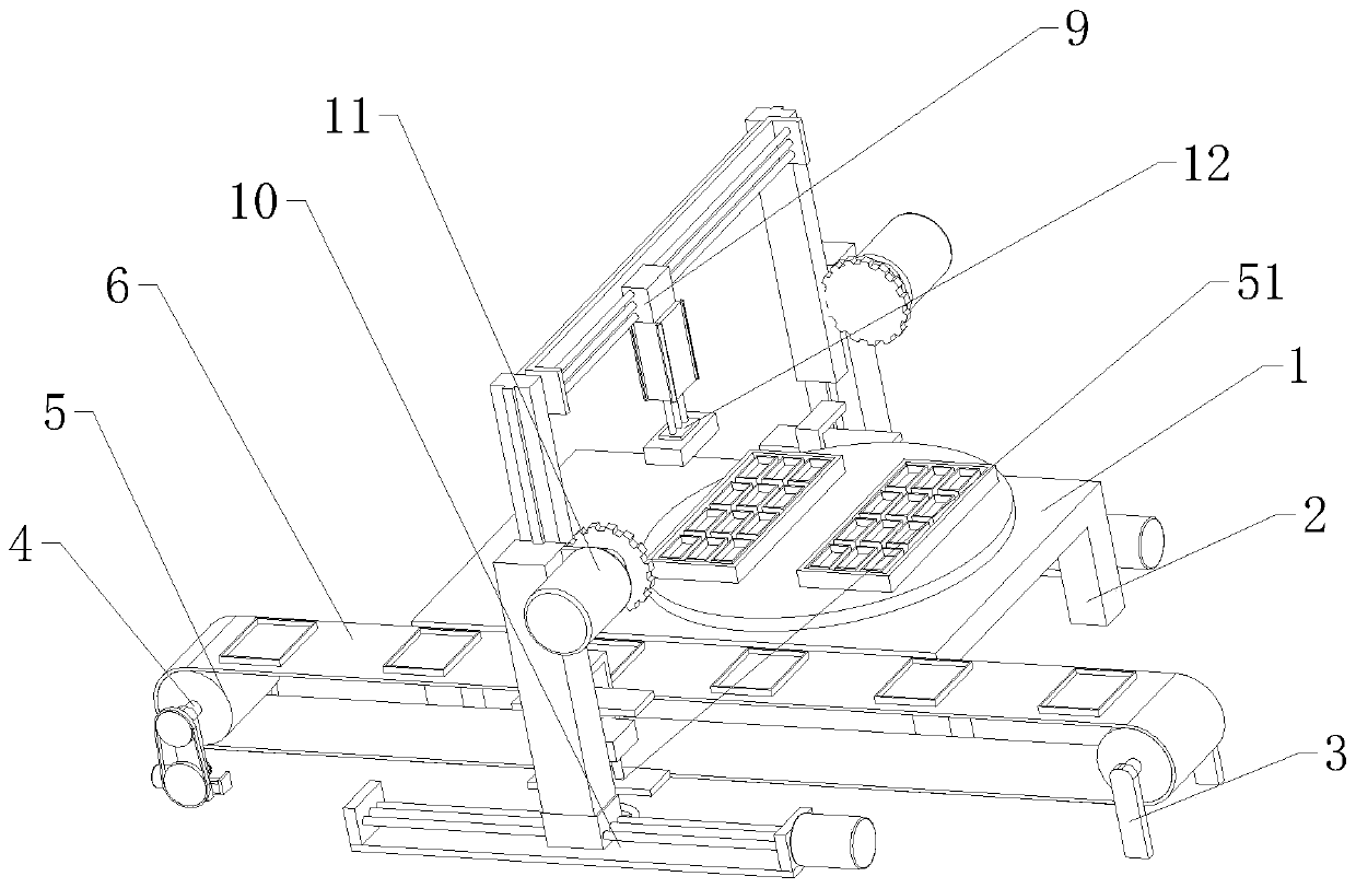
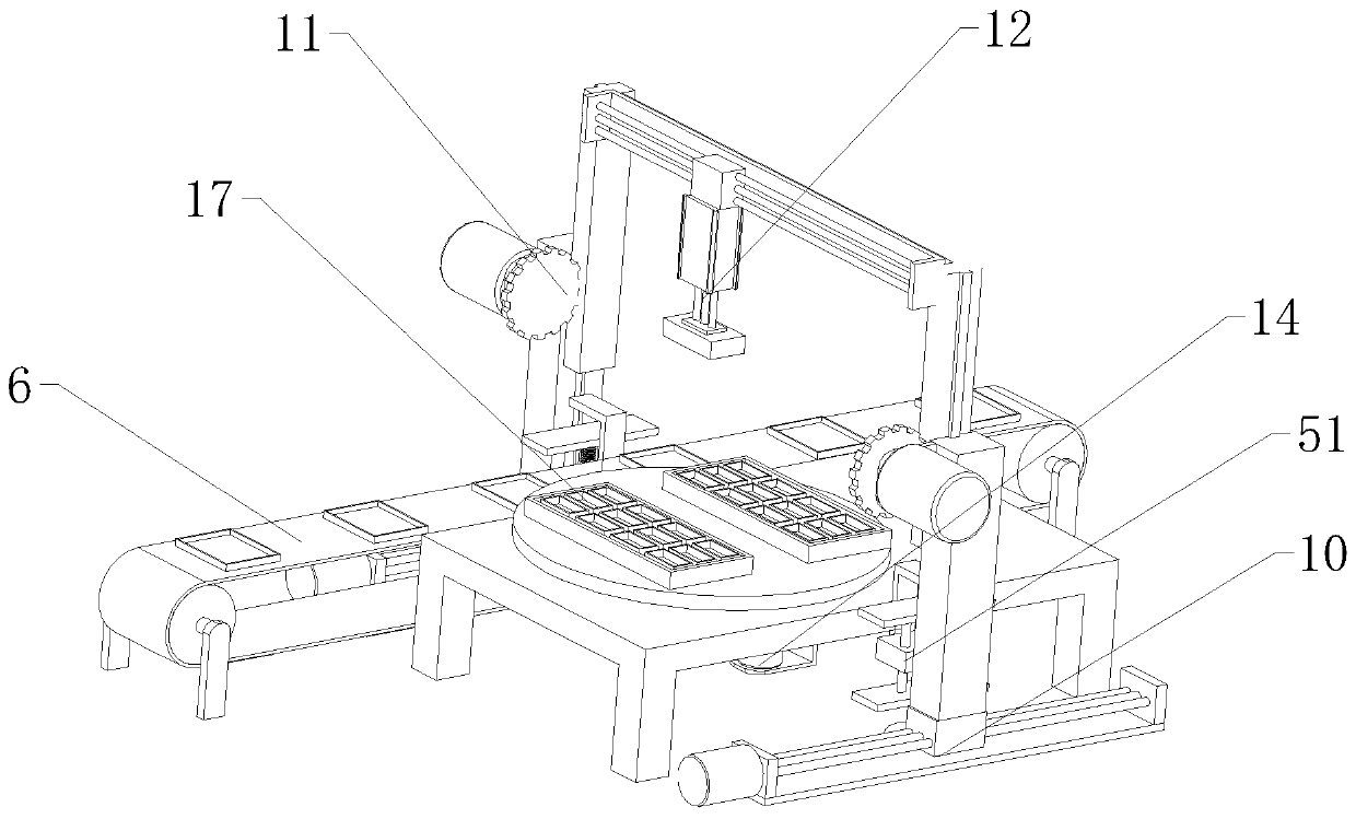
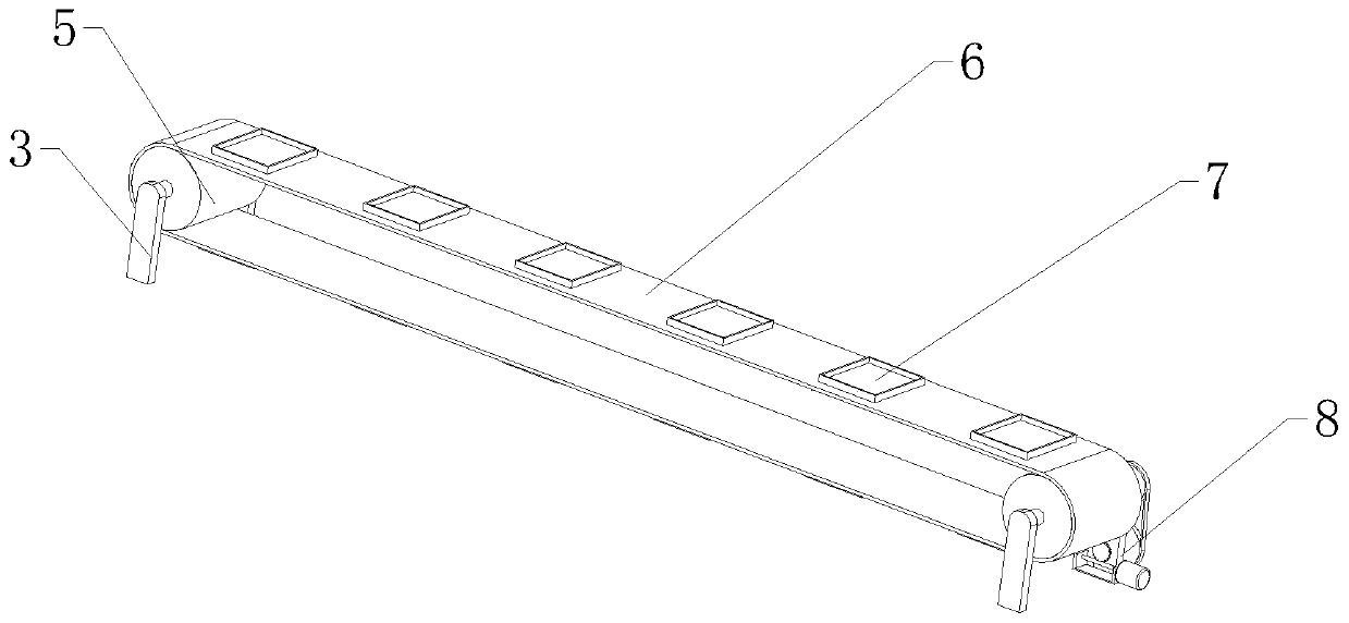
The invention relates to the technical field of automatic charging equipment, and specifically relates to an automatic chip charging device. The device comprises a working platform, and a conveying device which is arranged at the side part of the working platform, wherein the conveying device comprises a supporting frame, a roller, and a conveyor belt which sleeves the roller; the roller is fixedly arranged on the supporting frame; a driving assembly is arranged on the supporting frame; a picking and storing device is arranged at the upper parts of the working platform and the conveying device; the picking and storing device comprises a longitudinal moving mechanism and a lifting mechanism which are symmetrically arranged; the lifting mechanism is arranged on the output end of the longitudinal moving mechanism; a transverse moving mechanism is also connected to the output end of the lifting mechanism; a grabbing mechanism is arranged on the output end of the transverse moving mechanism; a jig device is arranged on the working platform; the jig device comprises a second rotating shaft which is shafted to the working platform; a rotating mechanism for driving the second rotating shaft to rotate is arranged at the bottom side of the working platform; and a turntable is fixedly mounted on the second rotating shaft. With the adoption of the device, the chip charging efficiency is improved.

Description

technical field [0001] The invention relates to the technical field of automatic feeding equipment, in particular to an automatic chip feeding device. Background technique [0002] Chip, also known as microcircuit (microcircuit), microchip (microchip), integrated circuit (English: integrated circuit, IC). Refers to silicon chips containing integrated circuits, which are small in size and are often part of computers or other electronic equipment. [0003] After the transistor was invented and mass-produced, various solid-state semiconductor components such as diodes and transistors were widely used, replacing the function and role of vacuum tubes in circuits. In the middle and late 20th century, the progress of semiconductor manufacturing technology made integrated circuits possible. Compared with hand-assembled circuits using individual discrete electronic components, integrated circuits can integrate a large number of tiny transistors into a small chip, which is a huge im...

Claims


Application Information

Patent Timeline
IPC IPC(8): B65G47/74B65G47/91
Inventor 夏安祥
Owner 夏安祥
Learn More