A sealing structure and method for a polysilicon reduction furnace

A technology of sealing structure and reduction furnace, applied in chemical instruments and methods, silicon compounds, inorganic chemistry, etc., can solve the problems of large number of bolts, high sealing requirements, weakened resilience, etc., to facilitate cleaning and recycling, and reduce costs , the close effect between

Active Publication Date: 2020-09-01
ASIA SILICON QINGHAI +1
View PDF2 Cites 0 Cited by
  • Summary
  • Abstract
  • Description
  • Claims
  • Application Information

AI Technical Summary

Problems solved by technology

However, polysilicon reduction furnaces are mostly pressurized equipment, which requires high sealing performance. At present, the bell jar and chassis of the reduction furnace are sealed with multiple sets of bolts for forced sealing. The number of bolts is large, and the tightness of each set of bolts is required to be high. The shutdown process is labor-intensive, and the sealing effect needs to be further confirmed; on the other hand, the gasket is squeezed for a long time under high temperature conditions, and the resilience is weakened, which is not conducive to reuse

Method used


Image

  • A sealing structure and method for a polysilicon reduction furnace
  • A sealing structure and method for a polysilicon reduction furnace
  • A sealing structure and method for a polysilicon reduction furnace

Examples


Embodiment 1

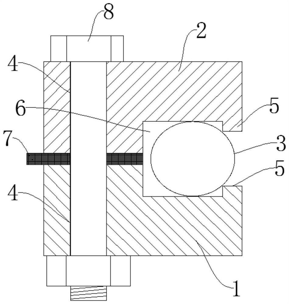
[0027] Embodiment 1, as shown in Figures 1-3, the present invention provides a polysilicon reduction furnace sealing structure, which is characterized in that it includes a reduction furnace chassis flange 1, a bell flange 2 and a flange 1 arranged on the reduction furnace chassis The metal backing ring 3 between the bell jar flange 2, the reduction furnace chassis flange 1 and the bell jar flange 2 are arranged oppositely, and the outer sides of the reduction furnace chassis flange 1 and the bell jar flange 2 are relatively evenly arranged There are bolt fixing holes 4, and the inner sides of the reduction furnace chassis flange 1 and the bell jar flange 2 are oppositely provided with stepped clamping platforms 5, the reduction furnace chassis flange 1, the bell jar flange 2 and the stepped clamping platforms 5 is a backing ring groove 6, the metal backing ring 3 is located in the backing ring groove 6, the metal backing ring 3 has elasticity, and the width of the upper and lo...

Embodiment 2

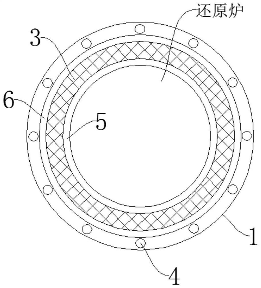
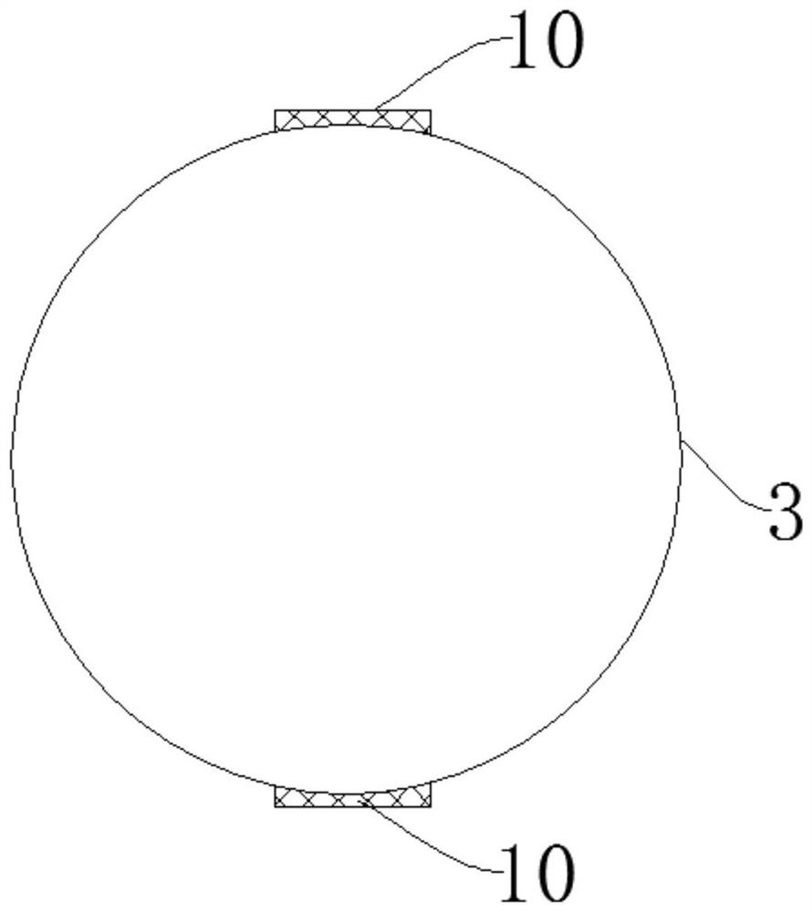
[0034] Embodiment 2, as shown in Figures 4-6, the present invention provides a polysilicon reduction furnace sealing structure, which is characterized in that it includes a reduction furnace chassis flange 1, a bell flange 2 and a flange 1 arranged on the reduction furnace chassis The metal backing ring 3 between the bell jar flange 2, the reduction furnace chassis flange 1 and the bell jar flange 2 are arranged oppositely, and the outer sides of the reduction furnace chassis flange 1 and the bell jar flange 2 are relatively evenly arranged There are bolt fixing holes 4, and the inner sides of the reduction furnace chassis flange 1 and the bell jar flange 2 are oppositely provided with stepped clamping platforms 5, the reduction furnace chassis flange 1, the bell jar flange 2 and the stepped clamping platforms 5 is a backing ring groove 6, the metal backing ring 3 is located in the backing ring groove 6, the metal backing ring 3 has elasticity, and the width of the upper and lo...

Embodiment 3

[0038]Embodiment 3, as shown in Figure 5, the present invention provides a sealing structure for a polysilicon reduction furnace, which is characterized in that it includes a reduction furnace chassis flange 1, a bell flange 2 and a method for setting the reduction furnace chassis The metal backing ring 3 between the flange 1 and the bell flange 2, the reduction furnace chassis flange 1 is set opposite to the bell flange 2, and the outer sides of the reduction furnace chassis flange 1 and the bell flange 2 are opposite Bolt fixing holes 4 are evenly arranged, and the inner sides of the reduction furnace chassis flange 1 and the bell jar flange 2 are oppositely provided with stepped clamping platforms 5, and the reduction furnace chassis flange 1, the bell jar flange 2 and the stepped type Between the decks 5 is a backing ring groove 6, the metal backing ring 3 is located in the backing ring groove 6, the metal backing ring 3 has elasticity, and the width of the upper and lower ...


PUM


Abstract

The invention discloses a polycrystalline silicon reduction furnace sealing structure and method. The sealing structure comprises a reducing furnace base plate flange, a bell jar flange and a metal pad rings, wherein the metal pad rings are arranged between the reducing furnace base plate flange and the bell jar flange; the reducing furnace base plate flange and the bell jar flange are in oppositearrangement; screw bolt fixing holes are uniformly formed in the outer sides of the reducing furnace base plate flange and the bell jar flange oppositely; step type clamp tables are arranged on the inner sides of the reducing furnace base plate flange and the bell jar flange oppositely; pad ring grooves are formed among the reducing furnace base plate flange, the bell jar flange and the step typeclamp tables; the metal pad rings are positioned in the pad ring grooves; the metal pad rings are elastic; in the natural state, the width of the upper and lower ends of the metal pad rings is greater than the height of the pad ring grooves. The rebounding force is provided through the self toughness of the metal materials; the sealing performance of the reducing furnace can be effectively ensured; through the inside and outside pressure differences, the surface of the metal rings is stressed from inside to outside; the rebounding force effect of the pad rings is further ensured; the sealingeffect is good; the cleaning is easy; the operation is convenient; the cyclic utilization can be realized.

Description

technical field [0001] The invention relates to the technical field of polysilicon production, in particular to a sealing structure and method for a polysilicon reduction furnace. Background technique [0002] Polysilicon is the basic material of the photovoltaic industry and the electronic information industry, with a wide range of applications and a large market demand. At present, most polysilicon production adopts the improved Siemens method, that is, the trichlorosilane purified to a certain standard and the hydrogen gas purified to the standard are used as materials, which are passed into the reduction furnace, and the materials are deposited on the surface of the electric heating silicon core through measures such as pressure and high temperature. Realize the process of "silicon rod growth", so as to achieve the purpose of producing polysilicon. However, polysilicon reduction furnaces are mostly pressurized equipment, which requires high sealing performance. At prese...

Claims


Application Information

Patent Timeline
Patent Type & Authority Patents(China)
IPC IPC(8): C01B33/035
Inventor 丁小海
Owner ASIA SILICON QINGHAI
Why Eureka
Try Eureka