
Intelligent interval pumping control method based on casing pressure test analysis

A control method and intelligent technology, which is applied in earthwork drilling, wellbore/well components, construction, etc., can solve problems such as failure to start and stop pumping units in time, difficulty in installation and debugging, and low control accuracy, so as to reduce manual labor The effect of strength, low cost, and simple calculation process

Active Publication Date: 2021-03-02
SHENYANG INST OF AUTOMATION - CHINESE ACAD OF SCI
View PDF6 Cites 0 Cited by
  • Summary
  • Abstract
  • Description
  • Claims
  • Application Information

AI Technical Summary

Problems solved by technology

The methods for determining the interval pumping system mainly include: the fixed time pumping method, which determines the interval pumping system based on experience, and cannot control the start and stop of the pumping unit in time according to the production status of the oil well; the manual intermittent pumping method, manually controls the pumping unit according to the oil well production Start and stop, high labor intensity, low control accuracy
At present, the main basis for intermittent pumping control is the dynamic liquid level or submergence and its change law. The dynamic liquid level monitors the intermittent pumping method, that is, by monitoring the change of the dynamic liquid level, pumping starts when the liquid level is high, and stops when the liquid level is low. Although this method realizes the automatic control of the start and stop of the pumping well, it needs to install the dynamic liquid level measurement equipment, which is difficult to install and debug, and the cost is high

Method used


Image

  • Intelligent interval pumping control method based on casing pressure test analysis
  • Intelligent interval pumping control method based on casing pressure test analysis
  • Intelligent interval pumping control method based on casing pressure test analysis

Examples


Embodiment Construction

[0027]The invention proposes an intelligent pumping control method based on casing pressure well test analysis.

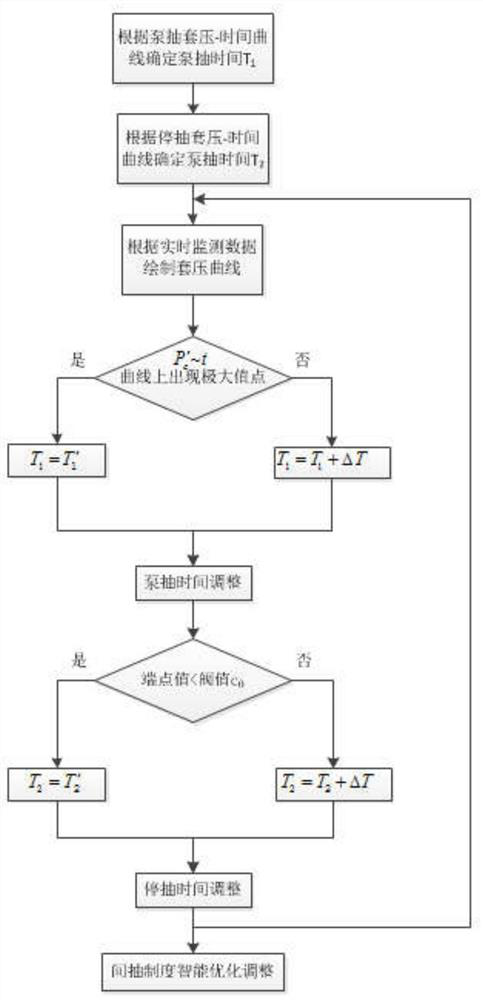
[0028]Such asimage 3As shown, the present invention includes the following steps:

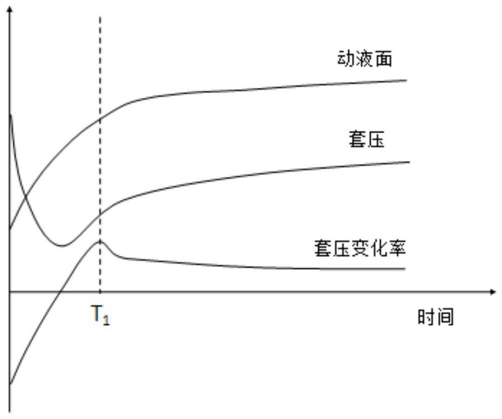
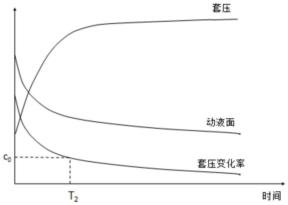
[0029]Step 1: Close the casing pressure valve, shut down the well for a period of time, and after the bottom of the well reaches a certain height, open the well for continuous and uninterrupted pumping, measure the casing pressure value during the pumping process, and draw the casing pressure-time relationship curve.

[0030]Step 2: According to the casing pressure-time relationship curve during pumping, draw the casing pressure change rate-time curve. The casing pressure change rate uses the following calculation formula:

[0031]

[0032]Where Pc′ Is the rate of change of casing pressure, ΔPcIs the amount of change in the casing pressure value within the time interval Δt.

[0033]On the casing pressure change rate-time relationship curve, take the time T corresponding to the maximum value of casing press...


PUM


Abstract

The invention relates to an intelligent intermittent pumping control method based on casing pressure well test analysis. According to the casing pressure-time relationship curve during the pumping period, the casing pressure change rate-time curve is drawn; the pumping time is determined as T 1 ; According to the casing pressure recovery curve during the withdrawal period, draw the casing pressure change rate-time curve; determine the withdrawal stop time as T 2 ; Oil well according to the interval pumping period T 1 +T 2 Run, draw the casing pressure-time relationship curve and casing pressure change rate-time curve during pumping period and stop pumping period respectively; update pumping time and stop pumping time according to the curve. The invention continuously monitors the casing pressure of the oil well, draws the casing pressure-time curve and the casing pressure change rate time curve, analyzes the variation law of the casing pressure and the dynamic liquid level, and determines the reasonable opening time and closing time; According to the production status, real-time optimization and adjustment of the pumping system is carried out to realize the intelligent control of low-yield and low-efficiency wells. While giving full play to the production potential of low-yield wells, the purpose of saving energy and reducing consumption and reducing the loss of pumping units and their equipment is achieved. .

Description

Technical field[0001]The invention relates to the field of intelligent control of the working system of a pumping well, in particular to an intelligent pumping control method based on casing pressure test analysis.Background technique[0002]In the process of oil and gas field development, due to low formation pressure, poor reservoir physical properties, and low oil layer seepage capacity, some oil wells have insufficient bottom hole liquid supply capacity, reduced oil well productivity, and reduced oil well system efficiency. If the liquid supply capacity is too low, the sucker pump will not work normally, causing serious liquid shock, which will cause the sucker pump to be damaged prematurely. Especially for low-permeability reservoirs, insufficient liquid supply is even more common. Severe liquid supply shortage will cause the occurrence of liquid hammer and evacuation, which will cause the oil pump to wear out, shorten its life, and waste electrical energy at the same time.[0003]...

Claims


Application Information

Patent Timeline
Patent Type & Authority Patents(China)
IPC IPC(8): E21B43/12E21B47/047E21B47/06
Inventor 曾鹏张立婷李世超郑东梁石硕于海斌
Owner SHENYANG INST OF AUTOMATION - CHINESE ACAD OF SCI
Learn More