Horizontal-type steam turbine condenser

A technology for condensers and steam turbines, applied in steam/steam condensers, non-rotating equipment cleaning, cleaning heat transfer devices, etc., can solve problems such as inability to eliminate supercooling, increase energy consumption, and increase cooling water consumption, etc., to achieve Avoid the increase of oxygen capacity, prevent clogging, and save dosage

Active Publication Date: 2019-06-14
大唐东营发电有限公司
View PDF9 Cites 2 Cited by
  • Summary
  • Abstract
  • Description
  • Claims
  • Application Information

AI Technical Summary

Problems solved by technology

[0007] However, the chamber composed of stainless steel plates is used for the passage of cooling water, which great

Method used


Image

  • Horizontal-type steam turbine condenser
  • Horizontal-type steam turbine condenser
  • Horizontal-type steam turbine condenser

Examples


Example Embodiment

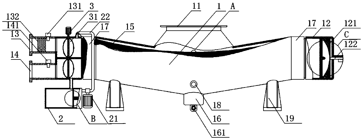
[0033] Example 1, see Figure 1-2 , 7-8, the present invention provides a technical solution: a horizontal steam turbine condenser, comprising a condenser cylinder 1, a throat 11, a support 19 and a cooling water pipe 15, the top of the condenser cylinder 1 The throat 11 is connected in the middle, and the bottom end is fixedly connected with supports 19 near both ends. The tube plate 17 is connected to both sides of the condenser cylinder 1, and the tube plate 17 on the left side of the condenser cylinder 1 The outer side is connected with a cooling water inlet chamber 13 and a cooling water outlet chamber 14, the tube sheet 17 on the right side of the condenser cylinder 1 is connected with a return water chamber end cover 12, and a cooling water pipe 15 is connected between the tube sheets 17, and the condensing steam A hot well 16 is arranged at the center of the bottom end of the condenser cylinder 1, and a condensed water outlet 161 is arranged at the bottom end of the he...

Example Embodiment

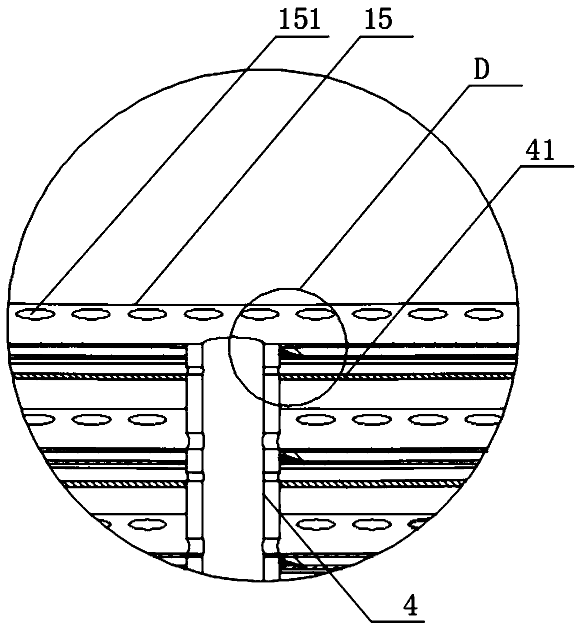
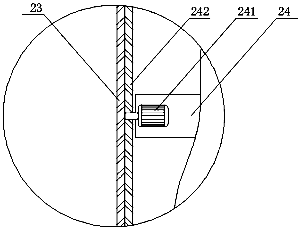
[0035] Example 2, see Figure 1-9 , the present invention provides a technical solution: a horizontal steam turbine condenser, comprising a condenser cylinder 1, a throat 11, a support 19 and a cooling water pipe 15, the top of the condenser cylinder 1 is connected to a Throat 11, and the bottom end near both ends is fixedly connected with support 19, both sides of condenser cylinder 1 are connected with tube plate 17, and the outer side of tube plate 17 on the left side of condenser cylinder 1 is connected with cooling The water inlet chamber 13 and the cooling water outlet chamber 14, the tube plate 17 on the right side of the condenser cylinder 1 is connected with the return water chamber end cover 12, the cooling water pipe 15 is connected between the tube plates 17, the condenser cylinder 1 A hot well 16 is arranged at the center of the bottom end of the hot well 16, and the bottom end of the hot well 16 is provided with a condensed water outlet 161, an air extractor 18 i...

Example Embodiment

[0037] Example 3, see figure 1 , 3 , 6, 9, the present invention provides a technical solution: a horizontal steam turbine condenser, comprising a condenser cylinder 1, a throat 11, a support 19 and a cooling water pipe 15, the top of the condenser cylinder 1 The throat 11 is connected in the middle, and the bottom end is fixedly connected with supports 19 near both ends. The tube plate 17 is connected to both sides of the condenser cylinder 1, and the tube plate 17 on the left side of the condenser cylinder 1 The outer side is connected with a cooling water inlet chamber 13 and a cooling water outlet chamber 14, the tube sheet 17 on the right side of the condenser cylinder 1 is connected with a return water chamber end cover 12, and a cooling water pipe 15 is connected between the tube sheets 17, and the condensing steam A hot well 16 is arranged at the center of the bottom of the condenser cylinder 1, and a condensed water outlet 161 is provided at the bottom of the heat we...


PUM


Abstract

The invention discloses a horizontal-type steam turbine condenser. The main viewing shape of each cooling water pipe is an arc which is opened upwards. Each cooling water pipe is of a thin-walled cavity structure. The cross section shape of each cooling water pipe is a major arc which is opened upwards. The lowest point in the horizontal direction of each cooling water pipe vertically communicateswith a condensed water guide pipe. The lowest points of the cooling water pipes are sequentially penetrated by the vertical condensed water guide pipe in the vertical direction, and flow guide holesare formed in the peripheries, corresponding to the lowest points of the cooling water pipes on the lower portion, of the condensed water guide pipe. Water receiving flow guide plates are arranged below the cooling water pipes in parallel, and the cross section shape of each water receiving flow guide plate is an arc which is opened upwards. The lowest point of each water receiving flow guide plate communicates with the condensed water guide pipe. A cooling water inlet chamber communicates with an automatic cleaning device used for cleaning the cooling water pipes. Condensed water condensed byeach cooling water pipe is independently guided to be discharged, supercooling happening due to the fact that the condensed water drips off onto the outer walls of the cooling water pipes on the lower portion is avoided and the blocking phenomenon of a cooling water channel can be effectively prevented.

Description

technical field [0001] The invention relates to the technical field of steam turbine condensers, in particular to a horizontal steam turbine condenser. Background technique [0002] The steam turbine, also known as the steam turbine engine, is a rotary steam power device. The high-temperature and high-pressure steam passes through the fixed nozzle to become an accelerated air flow and then sprays onto the blades, so that the rotor equipped with blade rows rotates and works externally. Steam turbines are the main equipment of modern thermal power plants, and are also used in metallurgical industry, chemical industry, and ship power plant. In the steam turbine power plant, the condenser is a very critical component, and its function is to condense the exhaust steam of the steam turbine into water, so it is also called a rehydrator. [0003] According to different steam condensation methods, condensers can be divided into surface type (also known as partition type) and mixed t...

Claims


Application Information

Patent Timeline
IPC IPC(8): F28B1/02F28B9/04F28B9/08F28B11/00F28G1/12F28G15/00
Inventor 李玮张元生贾长武倪培林李立东王永才陈鸿钊武卫卫刘磊付海
Owner 大唐东营发电有限公司
Why Eureka
Try Eureka