Current sensor and method for measuring an electric current

A technology of current sensor and resistance measurement, applied in the direction of measuring current/voltage, measuring electricity, components of electrical measuring instruments, etc., can solve the problems of deviation temperature and long transmission path.

Active Publication Date: 2019-06-14
CONTINENTAL AUTOMOTIVE TECH GMBH
View PDF8 Cites 3 Cited by
  • Summary
  • Abstract
  • Description
  • Claims
  • Application Information

AI Technical Summary

Problems solved by technology

However, such systems react to temperature changes in a delayed manner due to the long transmission path
In addition, elements with very good thermal conductivity also have thermal resistance, with the result that the temperature present at the temperature sensor may deviate slightly from the temperature of the measuring resistor

Method used


Image

  • Current sensor and method for measuring an electric current
  • Current sensor and method for measuring an electric current

Examples


Embodiment Construction

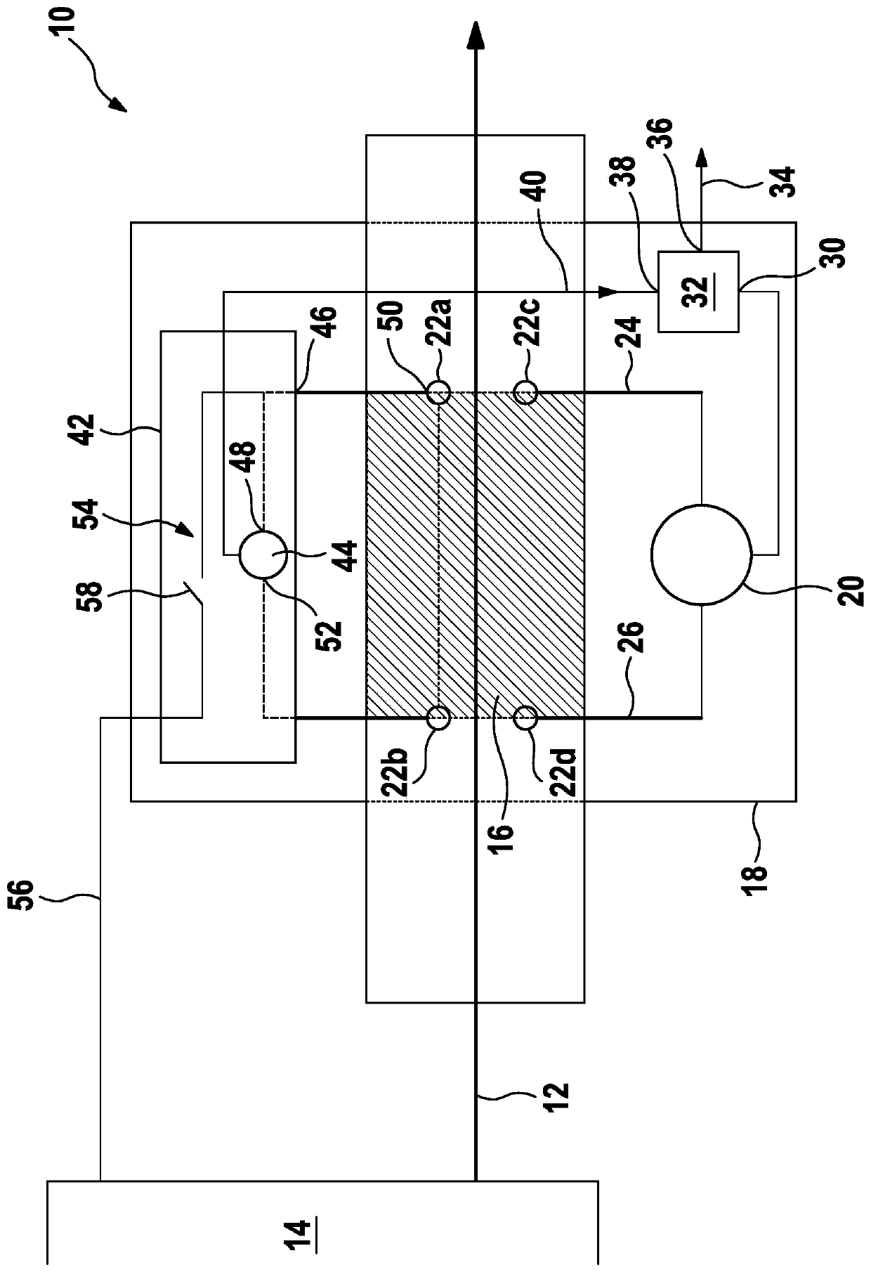
[0033] figure 1 A current sensor 10 for measuring a load current 12 of a battery 14 is shown. The battery 14 is, for example, a vehicle battery, the state of charge or state of health of which is intended to be defined by measuring the load current 12 .

[0034] The current sensor 10 has a measuring resistor 16 which can be electrically connected to the battery 14 such that the load current 12 of the battery 14 flows entirely via the measuring resistor 16 . Furthermore, current sensor 10 has a circuit carrier 18 on which measuring circuit 20 is arranged. The circuit carrier 18 is held on the measuring resistor 16 using a plurality of fixing pins 22a, 22b, 22c, 22d.

[0035] The measuring circuit 20 has a first measuring contact 24 and a second measuring contact 26, which are electrically connected to the measuring resistor 16 by means of corresponding fixing pins 22c, 22d, wherein the measuring contacts 24, 26 are at The current direction is electrically connected to the me...


PUM


Abstract

The invention relates to a current sensor (10), in particular for measuring a current of a battery (14), in particular a vehicle battery. The current sensor has at least one measuring resistor (16) and a circuit carrier (18), wherein the circuit carrier is fixed on the measuring resistor (16) by using at least one first retaining pin (22a); on the circuit carrier (18), a measuring circuit (20) fordetecting a voltage drop across the measuring resistor (16) is provided; and the first retaining pin (22a) consists of an electrically conductive material and is thermally conductively connected to the measuring resistor (16). Furthermore, at least one detection unit (42) is provided for detecting and outputting a temperature signal (40) of the first holding pin (22a).

Description

technical field [0001] The invention relates to a current sensor and a method for measuring the current, in particular of a battery, using such a current sensor. The current sensor has at least one measuring resistor and a circuit carrier, which is fastened to the measuring resistor using at least one first fastening pin. A measuring circuit for detecting the voltage drop across the measuring resistor is provided on the circuit carrier. Background technique [0002] Such current sensors are known in the prior art. The voltage drop across the measuring resistor is identified using this measuring circuit. Given the known resistance of the measuring resistor, the determined voltage drop can be used to identify the magnitude of the current flowing through the measuring resistor via Ohm's law, from which conclusions can be drawn about the state of charge of the battery. For this purpose, additional electrotechnical components can also be provided on the circuit carrier, for ex...

Claims


Application Information

Patent Timeline
Patent Type & Authority Applications(China)
IPC IPC(8): G01R19/00G01R1/20G01K7/16
CPCG01R31/36G01R1/203G01K7/16G01R15/14G01R15/146G01R19/0092G01R19/32G01K1/14G01R31/364G01R31/382
Inventor A·奥默尔
Owner CONTINENTAL AUTOMOTIVE TECH GMBH
Why Eureka
Try Eureka