Laser radar scanning method and laser radar

A technology of laser radar and scanning method, applied in radio wave measurement systems, instruments, etc., can solve the problems of complex methods and high requirements for production and debugging

Active Publication Date: 2019-06-14
LEISHEN INTELLIGENT SYST CO LTD
View PDF7 Cites 12 Cited by
  • Summary
  • Abstract
  • Description
  • Claims
  • Application Information

AI Technical Summary

Problems solved by technology

However, the multi-light source and multi-field of view stitching scheme includes the stitching process of multiple fields of view, the method is complicated, and it has high requirements for production debugging

Method used


Image

  • Laser radar scanning method and laser radar
  • Laser radar scanning method and laser radar
  • Laser radar scanning method and laser radar

Examples


Embodiment Construction

[0043] The present invention will be further described in detail below in conjunction with the accompanying drawings and embodiments. It should be understood that the specific embodiments described here are only used to explain the present invention, but not to limit the present invention. In addition, it should be noted that, for the convenience of description, only some structures related to the present invention are shown in the drawings but not all structures.

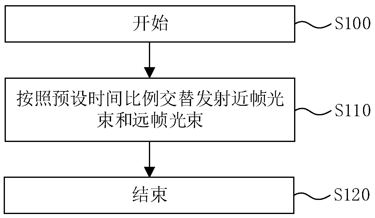
[0044] figure 1 It is a schematic flowchart of a lidar scanning method provided by an embodiment of the present invention. refer to figure 1 , the lidar scanning method includes:

[0045] S100, start.

[0046] Exemplarily, this step may include powering on the lidar, mode setting, parameter setting, and other preparations known to those skilled in the art before emitting the detection beam, which is not limited in this embodiment of the present invention.

[0047] S110. Alternately emit near-frame light beams ...


PUM


Abstract

The invention discloses a laser radar scanning method and a laser radar. The laser radar scanning method comprises the following steps that: according to a preset time interval, alternately emitting anear-frame light beam and a far-frame light beam, wherein the near-frame light beam has first field-of-view width A1 and first pulse frequency F1, the far-frame light beam has second field-of-view width A2 and second pulse frequency F2, A1 is greater than A2, and F1 is greater than F2. By use of the technical scheme provided by the embodiment of the invention, the near-frame light beam and the far-frame light beam are alternately emitted, different field-of-view widths and pulse frequencies can be used for meeting the detection requirements of different detection distances, and meanwhile, thescanning method is simple and is favorable for lowering requirements on production debugging.

Description

technical field [0001] Embodiments of the present invention relate to the technical field of laser radar, and in particular, to a laser radar scanning method and a laser radar. Background technique [0002] Lidar is a radar system that emits laser beams to detect characteristic quantities such as the position and speed of targets. The working principle of the laser radar is: to transmit a detection signal (laser beam) to the target, and then compare the received signal reflected from the target (target echo, or echo signal) with the transmitted signal, and then perform appropriate processing. Obtain the relevant information of the target, such as target distance, azimuth, height, speed, attitude, and even shape parameters, so as to detect, track and identify the target. The performance indicators of lidar include detection distance, field of view width, angular resolution and frame refresh rate (also can be understood as pulse frequency). Taking the lidar based on time of f...

Claims


Application Information

Patent Timeline
Patent Type & Authority Applications(China)
IPC IPC(8): G01S7/481
CPCG01S7/481
Inventor 胡小波沈俭
Owner LEISHEN INTELLIGENT SYST CO LTD
Why Eureka
Try Eureka