
A light spot detection camera and detection method of a spaceborne laser communication ATP system

A laser communication and space-borne technology, which is applied in photometry, image communication, and TV system components using electric radiation detectors, can solve problems such as low integration, tailing, and small detection front, and achieve Avoid halo phenomenon, improve frame rate, and avoid the effect of image data transmission

Active Publication Date: 2015-07-29
SHANGHAI INST OF TECHNICAL PHYSICS - CHINESE ACAD OF SCI
View PDF13 Cites 0 Cited by
  • Summary
  • Abstract
  • Description
  • Claims
  • Application Information

AI Technical Summary

Problems solved by technology

However, due to the defects in the structure of these detectors, there are still many shortcomings in the existing camera system: the four-quadrant avalanche tube detector has only four detection pixels, the detection array is small, and the pixel consistency is not good, which leads to the use of it as the basis. The designed detection camera has a small field of view, low detection probability and accuracy, and cannot flexibly change the tracking center; the CCD detector needs a variety of voltages to transfer signal charges, and has high power consumption. It can only be used with the cooperation of this kind of configuration circuit, which increases the complexity of the camera, and there is also a tailing phenomenon when the frame is transferred.
But up to now there is no spot detection camera based on CMOS detector applied in space laser communication ATP system

Method used


Image

  • A light spot detection camera and detection method of a spaceborne laser communication ATP system
  • A light spot detection camera and detection method of a spaceborne laser communication ATP system
  • A light spot detection camera and detection method of a spaceborne laser communication ATP system

Examples


Embodiment approach

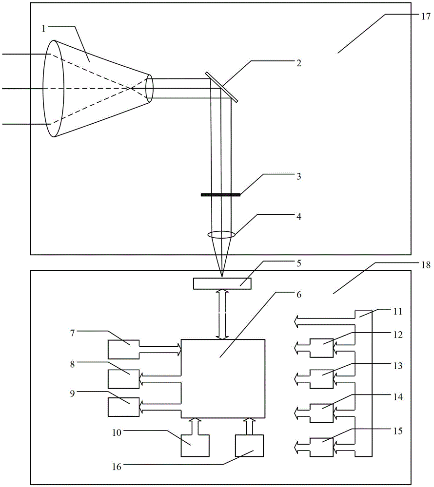
[0033] 1. After the camera starts to work, the FPGA configuration chip 10 (PROM chip XCF16PVO48C produced by XILINX) first writes the program into the FPGA chip 6 (XQ2VP40 field programmable array produced by XILINX). 5V voltage is provided by 5V DC power supply 11, 5V to 3.3V voltage conversion chip 12 (MSK5232-1.8HTS produced by MSK company) provides 3.3V voltage, 5V to 2.5V voltage conversion chip 13 (MSK5232-2.5HTS produced by MSK company) Provide 2.5V voltage, 5V to 1.8V voltage conversion chip 14 (MSK5232-1.8HTS produced by MSK company) provides 1.8V voltage, 5V to 1.5V voltage conversion chip 15 (MSK5232-1.5HTS produced by MSK company) Provide 1.5V voltage . The clock chip 16 (QT78LD9M-48MHZ produced by Q-TECH Company) provides the FPGA chip 6 with a 48MHz system operating clock.

[0034] 2. During space laser communication, the receiving telescope 1 (transmissive or reflective telescope system, with a magnification of 8 times) receives the beam, passes through the r...


PUM


Abstract

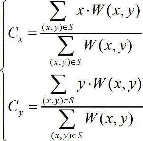
The invention discloses a space borne laser communication ATP (Acquisition Tracking Pointing) system spot detecting camera and a detecting method. The spot detecting camera and detecting method are used for detecting beaconing light direction of laser communication link so that the system gets an angular deviation of communication link beam direction to get position information of a communication terminal, thus establishing and maintaining the communication link. The spot detecting camera optical system is composed of a receiving telescope, a reflector, a bandpass optical filter and a taking lens and the spot detecting camera electronics system is composed of a 5-volt direct current power supply, a voltage conversion chip, an FPGA (field programmable gate array) chip, a CMOS (complementary metal oxide semiconductor) detector, a clock chip, a communication chip and the like. Beaconing light of the communication system is obtained through the optical system and an image is formed on the surface of the detector, then a spot centroid is obtained after the electronics system processes image data and is transmitted to a tracking system. High precision detection performance of the camera ensures that the ATP system can learn correctly of the communication terminal position and establish and maintain the stable communication link to guarantee the smooth achievement of space scale laser communication.

Description

Technical field: [0001] The invention relates to a detection camera and a detection method in an optical tracking and aiming system, in particular to a light spot detection camera and a detection method of a spaceborne laser communication ATP system. Background technique: [0002] In satellite-to-ground or inter-satellite laser communication, due to the long communication distance, narrow beam and external interference (such as atmospheric influence, satellite vibration, etc.), acquisition (Acquisition), tracking (Tracking) and aiming (Pointing) systems must be used to establish Maintain an optical communication link. The system is referred to as the ATP system. In the ATP system, one side of the communication link emits a wider beacon light to scan, and the other side searches for the beacon light. The beacon light enters the detector's field of view and is detected correctly. This process is called capture; after the ATP system captures the beacon light, both parties con...

Claims


Application Information

Patent Timeline
Patent Type & Authority Patents(China)
IPC IPC(8): H04N5/374H04N5/3745H04N5/376H04N5/378G02B23/02G01J1/42
Inventor 钱锋王建宇贾建军张亮杨攀杨明冬白帅张婷婷
Owner SHANGHAI INST OF TECHNICAL PHYSICS - CHINESE ACAD OF SCI
Learn More