Multi-mode power distribution cabinet

A power distribution cabinet, multi-mode technology, applied in substation/power distribution device shell, substation/switchgear cooling/ventilation, etc., can solve the problem of affecting the precision of electrical components, hindering the cooling effect of fans, and inaccurate control parameters, etc. problem, to achieve the effect of unimpeded circulation air path, increase the heat dissipation area, and enhance the cooling effect of the fan

Active Publication Date: 2019-06-14
安徽辉宝智能装备有限责任公司
View PDF5 Cites 4 Cited by
  • Summary
  • Abstract
  • Description
  • Claims
  • Application Information

AI Technical Summary

Problems solved by technology

[0003] For some high-voltage power distribution cabinets used for power distribution and control of high-end electromechanical equipment, especially the internal electrical components are more precise, so these precision electrical components have higher requirements on temperature conditions, the temperature fluctuates from high to low, or is too high or too high. Low will affect the precision of electrical components, resulting in inaccuracy of control parameters, and although the existing ordinary high-voltage power distribution cabinets have simple heat dissipation and heating components, it is often difficult to meet the relatively stable temperature conditions in the cabinet. The heating element is fixed installation, which not only poses a safety hazard, but also hinders the cooling effect of the fan

Method used


Image

  • Multi-mode power distribution cabinet
  • Multi-mode power distribution cabinet
  • Multi-mode power distribution cabinet

Examples


Embodiment Construction

[0028] The following will clearly and completely describe the technical solutions in the embodiments of the present invention with reference to the accompanying drawings in the embodiments of the present invention. Obviously, the described embodiments are only some, not all, embodiments of the present invention. Based on the embodiments of the present invention, all other embodiments obtained by persons of ordinary skill in the art without making creative efforts belong to the protection scope of the present invention.

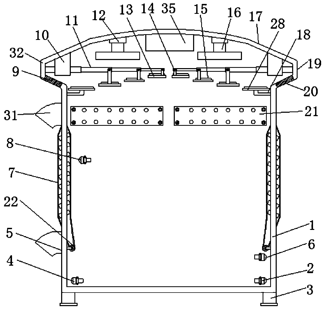
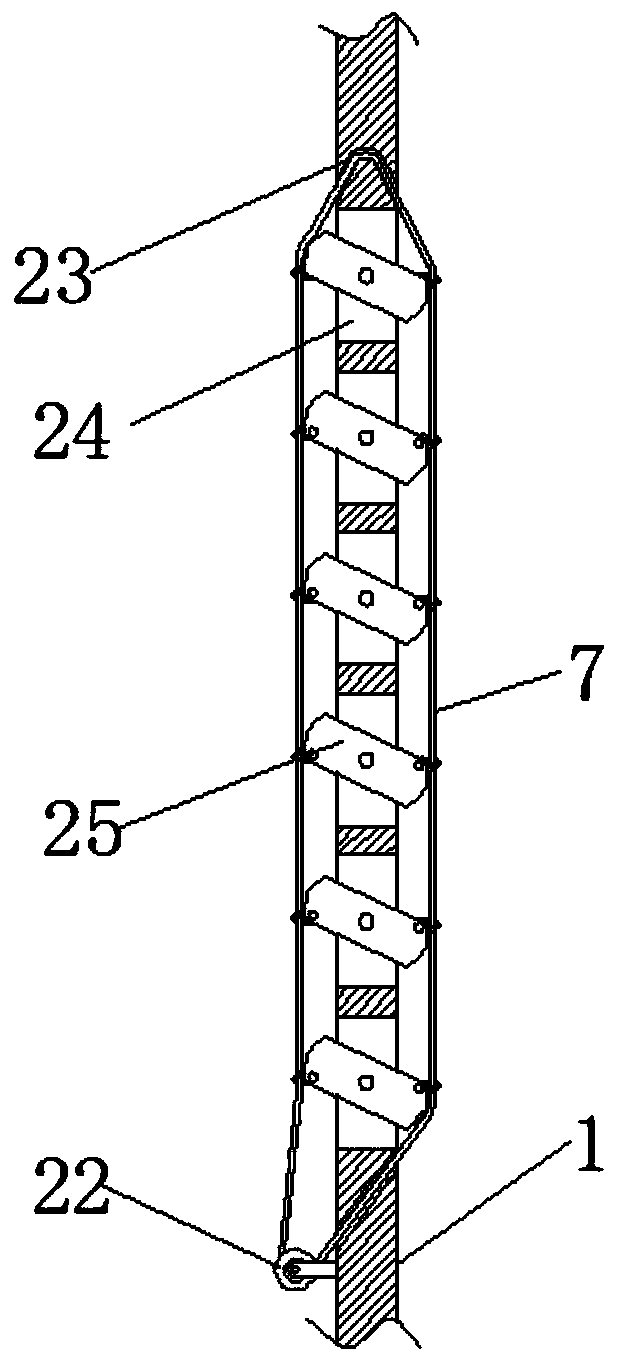
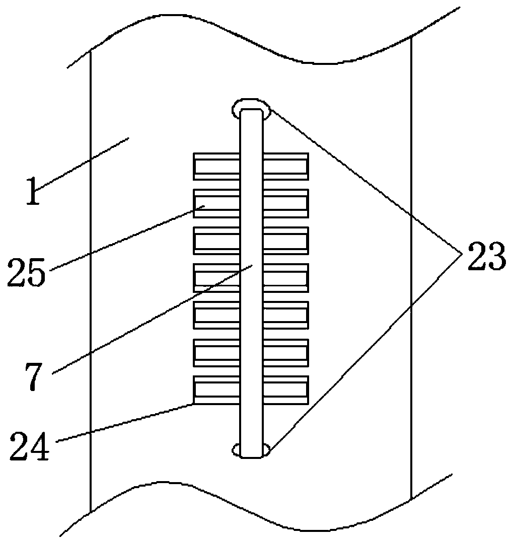
[0029] like Figure 1-5 As shown, a multi-mode power distribution cabinet includes a cabinet body 1, support feet 3 fixed on the four corners of the bottom surface of the cabinet body 1, and an electrical fixing plate 21 fixedly installed inside the cabinet body 1. One side wall of the cabinet body 1 has two upper and lower sides. Both ends are provided with threading openings 5, and the top of the cabinet body 1 is also fixedly connected with a top cover 32, an...


PUM


Abstract

The invention discloses a multi-mode power distribution cabinet. The multi-mode power distribution cabinet comprises a cabinet body, wherein a top cover is fixedly connected to the top end of the cabinet body; a circle of strip-shaped ventilation holes are formed in the side wall of the top cover, and fans are fixedly arranged on the two sides of the inner wall of the top end of the top cover respectively; two rows of insulation heat dissipation plates are hung above the inner part of the cabinet body through an electric telescopic rod and a corresponding connecting arm; electric heating wiresare fixed on the heat dissipation plates; a fourth temperature sensor and a third temperature sensor are further installed at the lower end of the interior of the cabinet body separately; a first temperature controller is further arranged in the cabinet body; a row of strip-shaped heat dissipation holes are formed in the side walls of the two ends of the cabinet body; the inner wall of each strip-shaped heat dissipation hole is rotationally connected with an air guide plate through a rotating shaft; and the air guide plate can adjust the opening degree of the strip-shaped heat dissipation holes. According to the multi-mode power distribution cabinet, a proper temperature can be kept by utilizing the heating wires when the temperature of the cabinet body is relatively low; meanwhile, different heat dissipation modes are adjusted according to different temperature values in the cabinet body, so that energy waste is avoided; and in addition, a heating assembly can be freely folded and put according to needs, so that the cabinet is convenient and practical.

Description

technical field [0001] The invention relates to the technical field of power distribution cabinets, in particular to a multi-mode power distribution cabinet. Background technique [0002] Power distribution cabinets are divided into power distribution cabinets, lighting distribution cabinets, and metering cabinets, and are the final equipment of the power distribution system. The power distribution cabinet is a general term for the motor control center. The power distribution cabinet is used in the occasions where the load is relatively scattered and there are few circuits; the motor control center is used in the occasions where the load is concentrated and there are many circuits. They distribute the electric energy of a certain circuit of the upper-level power distribution equipment to the nearest load. This level of equipment shall provide protection, monitoring and control of the load. [0003] For some high-voltage power distribution cabinets used for power distribut...

Claims


Application Information

Patent Timeline
Patent Type & Authority Applications(China)
IPC IPC(8): H02B1/30H02B1/28H02B1/56
Inventor 李贵
Owner 安徽辉宝智能装备有限责任公司
Why Eureka
Try Eureka