Ship motor brake control system
A motor braking and control system technology, applied in the control system, vector control system, motor generator control, etc., can solve the problems of increasing production cost and occupying space of the braking resistor box, so as to save production cost and achieve good stability and dynamic performance, the effect of low noise
- Summary
- Abstract
- Description
- Claims
- Application Information
AI Technical Summary
Problems solved by technology
Method used
Image
Examples
no. 1 example
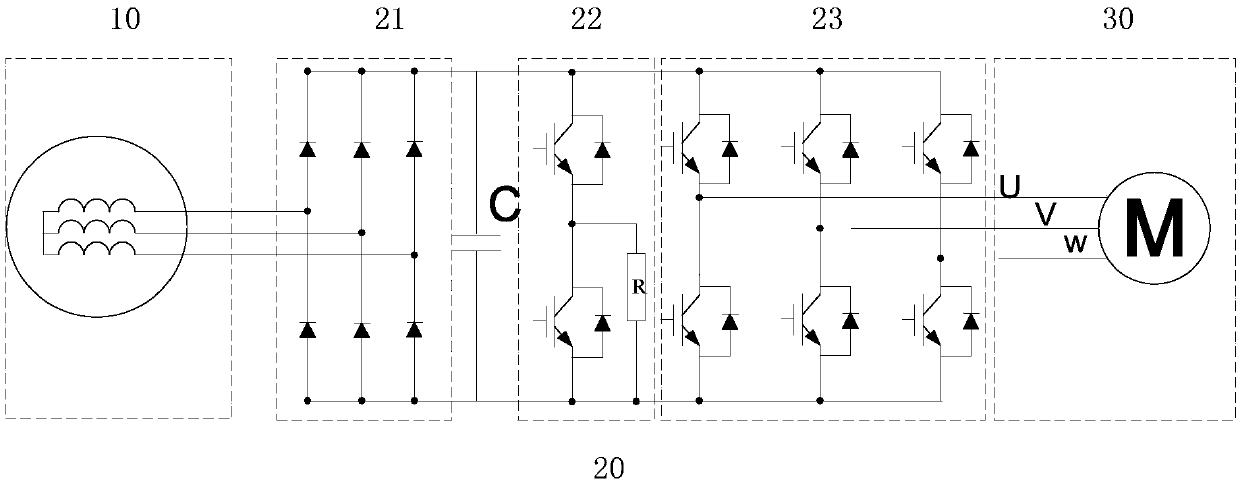
[0035] Such as figure 1 As shown, in the existing ship electric propulsion system, the generator winding 10 provides, for example, a 690V three-phase alternating current to the input end of the ship electric propulsion frequency converter 20, and the three-phase alternating current passes through the three-phase rectifying unit 21 in the frequency converter 20 Converted to a voltage of about 1050V, when braking, this voltage will be raised, and this voltage will be transmitted to the chopper resistance circuit 22, so the chopper resistance circuit 22 is also required to control the IGBT in it to perform chopper operation, or when the frequency conversion When the device fails, the IGBT in it is turned on for rapid discharge. The intermediate voltage is transmitted to the inverter main control unit 23 , and the inverter main control unit 23 further controls the opening and closing of the IGBTs of its three bridge arms to control the operation of the motor load 30 .
[0036] Fo...
PUM
 Abstract
Description
Claims
Application Information
 - R&D
- Intellectual Property
- Life Sciences
- Materials
- Tech Scout
- Unparalleled Data Quality
- Higher Quality Content
- 60% Fewer Hallucinations
Browse by: Latest US Patents, China's latest patents, Technical Efficacy Thesaurus, Application Domain, Technology Topic, Popular Technical Reports.
© 2025 PatSnap. All rights reserved.Legal|Privacy policy|Modern Slavery Act Transparency Statement|Sitemap|About US| Contact US: help@patsnap.com


