Condensed water collecting device of respirator

A technology for collecting device and condensing water, applied in respirator, chemistry, etc., can solve the problems of increasing patient mortality, increasing the incidence of ventilator-associated pneumonia, and no infection treatment methods

Pending Publication Date: 2019-06-18
THE FIRST AFFILIATED HOSPITAL OF WENZHOU MEDICAL UNIV
View PDF0 Cites 7 Cited by
  • Summary
  • Abstract
  • Description
  • Claims
  • Application Information

AI Technical Summary

Problems solved by technology

[0003] There is a water collection cup in the middle of the existing ventilator pipeline to collect condensed water. When the condensed water reaches a certain amount, it must be cleaned up in time, otherwise this humid environment is easy to colonize bacteria. The condensed water is an excellent bacterial bank, and pathogenic bacteria are easy to The parasitic reproduction here will increase the airway resistance and affect the patient's ventilation. At the same time, the condensed water stays for too long, which is conducive to bacterial reproduction. It may increase the incidence of ventilator-associated pneumonia and increase the mortality of patients by flowing to the patient's airway.
[0004] When the existing ventilator removes the water collection cup, the condensed water in the water collection cup may contain pathogenic bacteria and easily pollute the local environment, medical staff, and surrounding patients, causing nosocomial infection. In clinical practice, the medical staff need to wear gloves and manually remove the water collection cup Dump the condensed water, usually every 1-3 hours, the workload is huge; the ventilator is mostly used in the intensive care unit, it is easy to forget to replace the condensed water when the work is busy, and it needs to be reminded in time (currently the equipment does not have a reminder function); when dumping It may cause infection of staff and environmental pollution, and it is easy to pollute the environment of surrounding wards; currently there is no suitable treatment method for infection in the hospital; some equipment causes air pressure fluctuations in the ventilator pipeline due to the removal of the bottle

Method used


Image

  • Condensed water collecting device of respirator
  • Condensed water collecting device of respirator
  • Condensed water collecting device of respirator

Examples


Embodiment Construction

[0022] As required, detailed embodiments of the present invention are disclosed herein, but it should be understood that the disclosed embodiments are merely exemplary of the present invention, and the present invention can be implemented in different and alternative forms. The drawings are not necessarily drawn to scale, and certain features may be exaggerated or reduced to show details of specific components. Therefore, the specific structure and function details disclosed herein should not be construed as having a restrictive meaning, but only as a representative basis to teach those skilled in the art to use the present invention differently. Based on the embodiments of the present invention, all other embodiments obtained by those of ordinary skill in the art without creative work shall fall within the protection scope of the present invention.

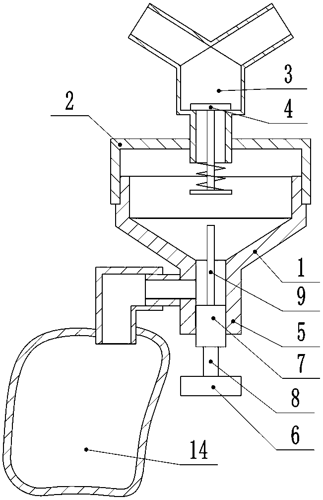
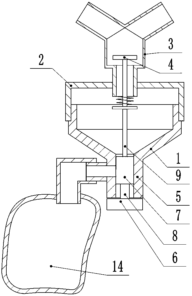
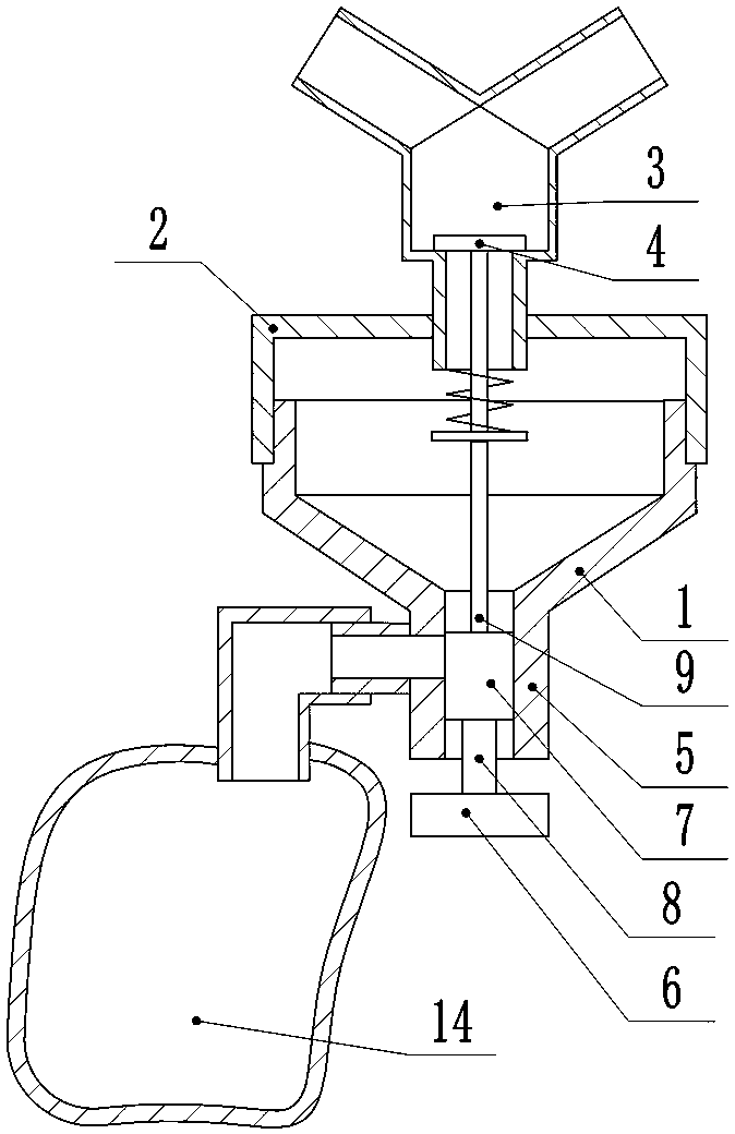
[0023] Such as figure 1 figure 2 image 3 As shown, a condensed water collection device for a ventilator includes a cup body 1 an...


PUM


Abstract

A condensed water collecting device of a respirator comprises a cup body and a cup cover, wherein a Y-shaped three-way joint is arranged on the cup cover, two channels on the upper portion of the three-way joint are connected with a respirator pipeline, a channel on the lower potion of the three-way joint is a condensed water channel, and the condensed water channel is provided with a valve element capable of controlling the condensed water channel to be opened and closed. A drainage pipeline is arranged on the lower portion of the cup body, and a valve body is arranged in the drainage pipeline and can control the opening and closing of the drainage pipeline; a linkage structure is designed between the valve body of the drainage pipeline and the valve element of the condensed water channel, so that when the valve body opens the drainage pipeline, the valve element closes the condensed water channel, and when the valve body closes the drainage pipeline, the valve element opens the condensed water channel.

Description

Technical field [0001] The invention belongs to the technical field of medical equipment, and relates to a collection cup, particularly a condensate collection device for a ventilator. Background technique [0002] The condensed water in the ventilator pipe and the water collection cup is an important place for bacteria to multiply. It has been reported that the positive rate of bacterial culture in condensed water is as high as 86.7%, and it was found that as high as 84.6% of the bacteria cultured from sputum. Bacteria can be cultivated from the ventilator pipes and condensed water. Condensate is an important factor that causes ventilator-associated pneumonia (VAP). Condensed water in the ventilator pipeline will reduce the inner diameter of the pipeline, thereby increasing the airway resistance, increasing the patient's inhalation work, and reducing the tidal volume. Therefore, the condensate must be poured out in time, otherwise it is easy to cause the condensate to pollute ...

Claims


Application Information

Patent Timeline
Patent Type & Authority Applications(China)
IPC IPC(8): A61M16/08A61M16/00A61L2/18
Inventor 谢强丽陈必成项俊之
Owner THE FIRST AFFILIATED HOSPITAL OF WENZHOU MEDICAL UNIV
Why Eureka
Try Eureka