Simple and convenient reinforcing steel bar straightening tool

A steel bar and straightening technology, applied in the field of tools, can solve the problems of small number of end wrenches, inconvenient use, affecting the quality and progress of the project, and achieve the effects of ensuring integrity and functionality, reducing engineering costs, and facilitating production

Inactive Publication Date: 2019-06-18
MCC5 GROUP CORP SHANGHAI
View PDF5 Cites 2 Cited by
  • Summary
  • Abstract
  • Description
  • Claims
  • Application Information

AI Technical Summary

Problems solved by technology

[0002] During the engineering construction process, it is often necessary to leave a certain overlapping length of the steel bars and carry out the construction process twice. Since the steel bars are exposed and have been installed in the corresponding positions, it is very easy to cause bumps on the exposed steel bars during construction in other processes, making the exposed steel bars Deformation and bending of steel bars, especially pile head steel bars and deformation joint steel bars are more serious. The traditional method uses manpower to straighten the steel bars with sticks or steel pipes, and it is difficult to meet the quality requirements, especially in areas where the diameter of the steel bars is thick and the spacing between the steel bars is too dense. It is difficult to operate the construction under such circumstances, and the existing straightening methods and straightening tools are not rigid enough, the number of end wrenches is small, inconvenient to use, unable to be reused, and low efficiency, which leads to the disadvantages of steel bar spacing and protective layer thickness. Hidden dangers that cannot meet the design and specification requirements further affect the quality and progress of the project
[0003] Therefore, there are above-mentioned inconveniences and problems in known straightening methods and straightening tools

Method used


Image

  • Simple and convenient reinforcing steel bar straightening tool
  • Simple and convenient reinforcing steel bar straightening tool
  • Simple and convenient reinforcing steel bar straightening tool

Examples


Embodiment 1

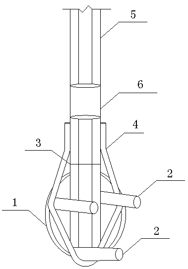
[0027] The simple steel bar straightening tool of the present invention comprises a straightening head, a handle and a sleeve.

[0028] see now figure 1 , figure 1 It is a structural schematic diagram of a steel bar straightening tool according to an embodiment of the present invention. As shown in the figure, the straightening head includes a circular plate 1, three straightening rods 2, a connecting rod 3, and a hoop 4. The circular plate is a circular steel plate with a diameter ≥ 140 mm and a thickness ≥ 12 mm; the three straightening rods are three Short steel bars, each short steel bar has a diameter of 25mm and a length of 100mm, and the three short steel bars are arranged in an isosceles triangle on the surface of the circular steel plate. The distance between the three straightening rods should be greater than 60mm, and each short steel bar is perpendicular to the circular plate; A number of steel bars are bundled and welded together to form the first steel tendon. ...

Embodiment 2

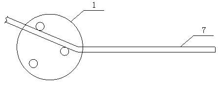
[0032] Simple steel bar straightening tool using method of the present invention:

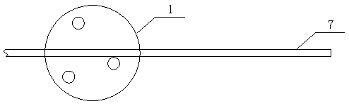
[0033] When the steel bar is straightened, the on-site operator holds the handle with both hands, clamps any two of the straightening rods on both sides of the bent part of the steel bar, pushes the handle to the adjustment direction required by the steel bar, and repeats fine-tuning until the The straight state required by the steel bar to achieve the straightening effect of the steel bar. figure 2 It is a schematic diagram of the use state of the steel bar straightening tool of the embodiment of the present invention, image 3 It is a schematic diagram of straightening the steel bar 7 to be straightened according to the embodiment of the present invention.

[0034] The present invention has substantive features and significant technical progress. The simple steel bar straightening tool of the present invention can effectively straighten bent and deformed steel bars while maintaining quality...


PUM

PropertyMeasurementUnit
lengthaaaaaaaaaa
diameteraaaaaaaaaa
diameteraaaaaaaaaa

Abstract

The invention discloses a simple and convenient reinforcing steel bar straightening tool. The simple and convenient reinforcing steel bar straightening tool comprises a straightening head, a handle and a sleeve, and is characterized in that the straightening head comprises a circular plate, three straightening rods, a connecting rod and a holding hoop; the circular plate is a circular steel platewith the diameter of greater than or equal to 140 mm and the thickness of greater than or equal to 12 mm; the three straightening rods are three short reinforcing steel bars; the handle is a second reinforcing steel bar bundle which is formed by bundling, fixing and welding a plurality of reinforcing steel bars together; the reinforcing steel bar location of the second reinforcing steel bar bundleis the same as that of a first reinforcing steel bar bundle; the length of the second reinforcing steel bar bundle is greater than or equal to 1,500 mm; screw threads are formed in one end of the second reinforcing steel bar bundle; the sleeve is a straight threaded reinforcing steel bar sleeve; and the sleeve is connected between the first reinforcing steel bar bundle and the second reinforcingsteel bar bundle through the screw threads. The simple and convenient reinforcing steel bar straightening tool disclosed by the invention has the advantages that the tool is simple in structure and convenient to manufacture; a bent and deformed reinforcing steel bar can be effectively straightened with guaranteed quality and quantity when a reserved reinforcing steel bar is collided so as to ensure the integrity and the functionality of reinforcing steel bar engineering; the straightening tool can be recycled; materials are saved; and the engineering cost is reduced.

Description

technical field [0001] The invention relates to a tool used in the construction of steel bars, in particular to a simple tool for straightening steel bars. Background technique [0002] During the engineering construction process, it is often necessary to leave a certain overlapping length of the steel bars and carry out the construction process twice. Since the steel bars are exposed and have been installed in the corresponding positions, it is very easy to cause bumps on the exposed steel bars during construction in other processes, making the exposed steel bars Deformation and bending of steel bars, especially pile head steel bars and deformation joint steel bars are more serious. The traditional method uses manpower to straighten the steel bars with sticks or steel pipes, and it is difficult to meet the quality requirements, especially in areas where the diameter of the steel bars is thick and the spacing between the steel bars is too dense. It is difficult to operate th...

Claims


Application Information

Patent Timeline
Patent Type & Authority Applications(China)
IPC IPC(8): B21F1/02
Inventor 赵鹏飞
Owner MCC5 GROUP CORP SHANGHAI
Why Eureka
Try Eureka