Demolding integrated mold for inner wall grid high rib barrel-shaped thin-wall part and forming method

A technology of thin-walled parts and grid ribs, which is applied in the direction of manufacturing tools, forging/pressing/hammer devices, forging/pressing/hammering machinery, etc., can solve the problems of high cost and complicated process, and reduce manufacturing costs and Effect of production cost, reduction of labor cost and raw material cost

Inactive Publication Date: 2019-06-18
BEIJING HANGXING MACHINERY MFG CO LTD
View PDF5 Cites 6 Cited by
  • Summary
  • Abstract
  • Description
  • Claims
  • Application Information

AI Technical Summary

Problems solved by technology

[0003] The technical problem solved by the present invention is: to overcome the deficiencies of the prior art, to provide an integrated mold and forming method for the demoulding of the inner wall grid high-strength barrel-shaped thin-walled parts, so as to solve the existing problem of forming such metal barrel-shaped structural parts. Methods (such as machining thick-walled barrels with high ribs, and fixing high-rib strips on the plate by welding or riveting) have high cost and complicated procedures, so as to realize the overall forming of large-scale inner-wall grid high-rib barrel-shaped components

Method used


Image

  • Demolding integrated mold for inner wall grid high rib barrel-shaped thin-wall part and forming method
  • Demolding integrated mold for inner wall grid high rib barrel-shaped thin-wall part and forming method
  • Demolding integrated mold for inner wall grid high rib barrel-shaped thin-wall part and forming method

Examples


Embodiment 1

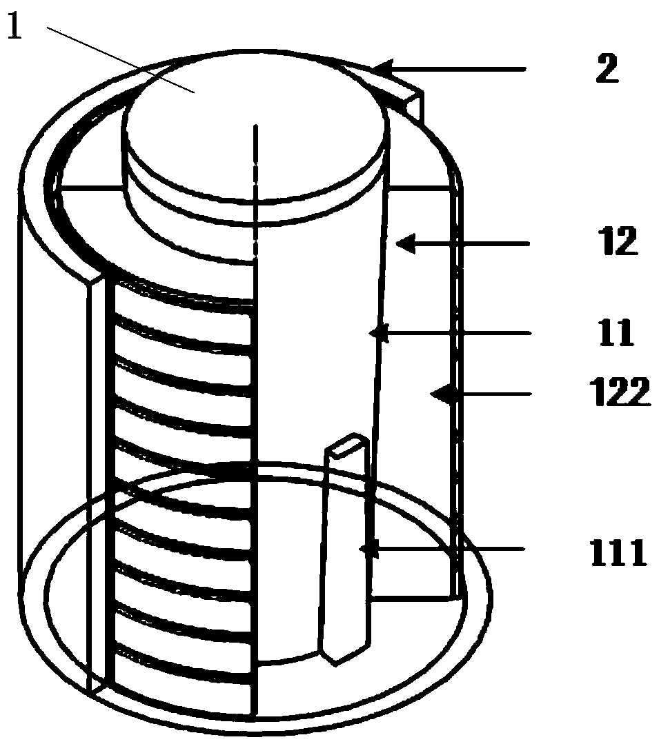
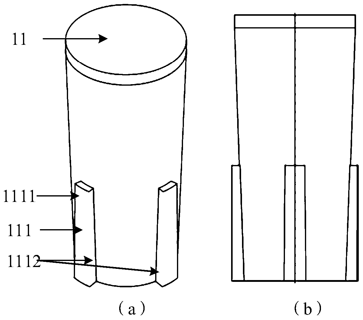
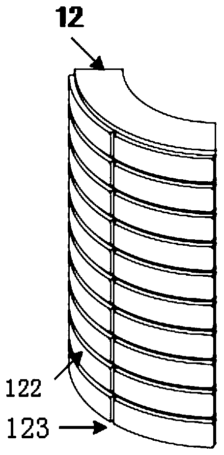
[0046] Such as Figure 1~5 As shown, the mold mainly includes a combined punch 1 (punch mandrel and multiple punch inserts), and a die 2. The material selected is low heat-resistant high-toughness steel 5CrMnMo. After heat treatment, it has sufficient strength, Hardness and wear resistance, the combined punch is divided into a punch mandrel 11 and a punch insert 12, and the upper and lower surfaces of the combined punch 1 and the die 2 are horizontal. The contact surface of the punch mandrel 11 and the punch insert 12 should be designed as a wedge mechanism, the surface has been ground and polished, the surface roughness of the punch and die is Ra0.8, the punch mandrel 11 and the punch insert 12 It should be designed as a matching relationship with a slope, and the angle is 2°-5°. The slider 111 of the punch mandrel 11 is in clearance fit with the groove 121 of the punch insert 12 , and the slider 111 and the groove 121 move without interference during extrusion. The sliders...

Embodiment 2

[0049] Such as Figure 1~5 As shown, the mold mainly includes a combined punch 1 (punch mandrel and multiple punch inserts), and a die 2. The material selected is low heat-resistant high-toughness steel 5CrMnMo. After heat treatment, it has sufficient strength, Hardness and wear resistance, the combined punch is divided into a punch mandrel 11 and a punch insert 12, and the upper and lower surfaces of the combined punch 1 and the die 2 are horizontal. The contact surface of the punch mandrel 11 and the punch insert 12 should be designed as a wedge mechanism, the surface has been ground and polished, the surface roughness of the punch and die is Ra0.8, the punch mandrel 11 and the punch insert 12 It should be designed as a matching relationship with a slope, and the angle is 2°-5°. The slider 111 of the punch mandrel 11 is in clearance fit with the groove 121 of the punch insert 12 , and the slider 111 and the groove 121 move without interference during extrusion. The sliders...


PUM


Abstract

The invention discloses a demolding integrated mold for an inner wall grid high rib barrel-shaped thin-wall part and a forming method. The mold comprises a convex mold and a concave mold, wherein theconvex mold comprises a convex mold mandrel and a plurality of convex mold inserts. The diameter of the periphery of the convex mold mandrel is gradually decreased from the top end to the bottom end.The convex mold inserts form a cylinder arranged on the periphery of the convex mold mandrel in a sleeving manner. A plurality of toroidal rib grooves and a plurality of vertical rib grooves are formed in the outer surface of each convex mold insert, and the toroidal rib grooves and the vertical rib grooves are arranged in a staggered manner to form a plurality of mesh blocks. The concave mold isarranged on the periphery of the convex mold in a sleeving manner. The forming method solves the problems of high cost, complex steps and the like of an existing forming method (for example, machininghigh ribs on a thick-wall barrel and fixing the high ribs to a panel by way of welding or riveting) of a metal barrel-shaped structural part, so that a large inner wall grid high rib barrel-shaped member is formed integrally.

Description

technical field [0001] The invention belongs to the technical field of inner-wall grid high-strength barrel-shaped thin-walled parts, and in particular relates to an integrated demoulding mold and forming method for inner-wall grid high-rib barrel-shaped thin-walled parts. Background technique [0002] With the continuous acceleration of my country's economic globalization process, whether it is aerospace or automobiles, reducing energy consumption and increasing payload, lightweighting of large structural parts has become one of the research hotspots. For metal materials that are maturely used in the market, while ensuring the same structural strength, reducing the weight of the plate, ribbed structural parts have become a direct and effective way to achieve lightweight. Therefore, a large number of products have deep inner cavities and distributed grids. Structural stiffener plate barrel structural members. In order to realize the preparation of this type of structural pa...

Claims


Application Information

Patent Timeline
Patent Type & Authority Applications(China)
IPC IPC(8): B21J13/02B21J5/02
Inventor 李建伟张铁军郭晓琳
Owner BEIJING HANGXING MACHINERY MFG CO LTD
Why Eureka
Try Eureka