Machining fixing tool for special-shaped valve seat part

A technology for fixing tooling and valve seats, applied in positioning devices, metal processing equipment, metal processing machinery parts, etc., can solve problems affecting product quality and processing efficiency, large quantities, error accumulation, etc. The effect of shortening the process flow and reducing the number of tooling

Inactive Publication Date: 2019-06-18
CHENGDU AIRCRAFT INDUSTRY GROUP
View PDF5 Cites 1 Cited by
  • Summary
  • Abstract
  • Description
  • Claims
  • Application Information

AI Technical Summary

Problems solved by technology

[0002] The shape and structure of special-shaped valve seat parts are complex and small in size. Over the years, ordinary machine tools have been used for processing. This processing method not only has a long process flow and a long processing cycle, but also requires a large number of special tooling. Clamping will also produce error accumulation, seriously affecting product quality and processing efficiency
Especially when milling the inner cavity of a part, the operator needs to manually turn the angle of the milling machine spindle back and forth to ensure the angle of the inner cavity. Human factors are large and the processing efficiency is low. The emergence of turn-milling combined processing technology has solved this problem. Turning and milling compound machining is one-time clamping, which integrates all functions of CNC turning and milling, and can complete turning, milling, drilling, boring, B-axis turning, five-axis linkage and other processing

Method used


Image

  • Machining fixing tool for special-shaped valve seat part
  • Machining fixing tool for special-shaped valve seat part
  • Machining fixing tool for special-shaped valve seat part

Examples


Embodiment 1

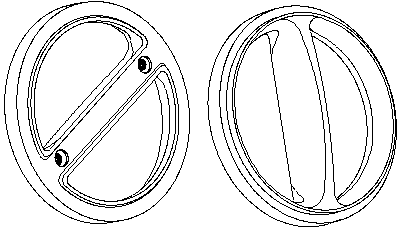
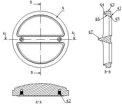
[0030] The structure of special-shaped valve seat part 4 in the prior art is as figure 1 and figure 2 As shown, its front features are two semicircular bosses 41, two threaded holes 42, part 4 large outer circle 43, part 4 back step outer circle 44 and two straight groove semicircles 45, the semicircular convex The platform 41 is in the same direction as the semicircle features of the two elevation angle curved surfaces 46 of the inner cavity of the part 4;

[0031] For the above-mentioned special-shaped valve seat part 4, this embodiment provides a processing and fixing tool for the special-shaped valve seat part, including a clamp base and a compression ring 1. Connected clamping part 2, the clamping part 2 is arranged on the positioning seat 3 at the end away from the part 4, and the front end of the positioning seat 3 is provided with a shallow groove that just accommodates two semicircular bosses 41 on the front of the part 4 32, the surface of the shallow groove 32 is...

Embodiment 2

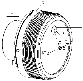
[0034] As a preferred implementation mode, this embodiment provides a processing and fixing tool for special-shaped valve seat parts, such as image 3 and Figure 4 As shown, it includes a clamp base and a compression ring 1. The clamp base includes a positioning seat 3 and a clamping part 2 for connecting with the spindle chuck of the machine tool. The clamping part 2 is arranged on the positioning seat 3 away from the part 4 one end, the front end surface of the positioning seat 3 is provided with a shallow groove 32 that just accommodates the two semicircular bosses 41 on the front of the part 4, and the surface of the shallow groove 32 is provided with a positioning position corresponding to the threaded hole 42 on the part 4. Pin 6, the inner wall of the top of the compression ring sleeve 1 is provided with a circle of limit boss 12, the center of the limit boss 12 forms an opening that fits with the outer circle 44 of the step on the back of the part 4, and the compressi...

Embodiment 3

[0038] As the best implementation mode, this embodiment provides a processing fixture for special-shaped valve seat parts, including a clamp base and a compression ring 1, the clamp base includes a positioning seat 3 and is used to connect with the machine tool spindle chuck The clamping part 2, the clamping part 2 is set on the positioning seat 3 at the end away from the part 4, the front end of the positioning seat 3 is provided with a shallow groove 32 that just accommodates the two semicircular bosses 41 on the front of the part 4 , the surface of the shallow groove 32 is provided with a positioning pin 6 corresponding to the threaded hole 42 on the part 4, and the inner wall of the top end of the pressing ring 1 is provided with a circle of limiting bosses 12, and the center of the limiting boss 12 is An opening that fits in a gap with the outer circle 44 of the step on the back of the part 4 is formed, and the compression ring 1 and the positioning seat 3 are connected wi...


PUM


Abstract

The invention discloses a machining fixing tool for a special-shaped valve seat part, and belongs to the field of tool clamps. The tool comprises a clamp base body and a pressing ring sleeve; the clamp base body comprises a positioning seat and a clamping part arranged at the end, far away from the part, of the positioning seat; a shallow groove which just contains two semicircular bosses on the front surface of the part is formed in the end surface of the front end of the positioning seat; a positioning pin corresponding to a threaded hole in the part is arranged on the surface of the shallowgroove; a circle of limiting boss is arranged on the inner wall of the top end of the pressing ring sleeve; a hole which is in clearance fit with a part back step outer circle is formed in the centerof the limiting boss; and the pressing ring sleeve and the positioning seat are in matched connection to fasten the part between the positioning seat and the pressing ring sleeve. The machining fixing tool is simple in structure and convenient to use, the whole part can be machined through twice clamping, the number of tools can be reduced, technological process can be shortened, the positioningerror is small, and the processing efficiency is high.

Description

technical field [0001] The application relates to the field of mechanical processing, in particular to a processing and fixing tool for special-shaped valve seat parts. Background technique [0002] The shape and structure of special-shaped valve seat parts are complex and small in size. Over the years, ordinary machine tools have been used for processing. This processing method not only has a long process flow and a long processing cycle, but also requires a large number of special tooling. Clamping will also produce error accumulation, seriously affecting product quality and processing efficiency. Especially when milling the inner cavity of a part, the operator needs to manually turn the angle of the milling machine spindle back and forth to ensure the angle of the inner cavity. Human factors are large and the processing efficiency is low. The emergence of turn-milling combined processing technology has solved this problem. Turning and milling compound machining is a one-...

Claims


Application Information

Patent Timeline
Patent Type & Authority Applications(China)
IPC IPC(8): B23Q3/12
Inventor 汪小东陈思涛冯小亮刘擎
Owner CHENGDU AIRCRAFT INDUSTRY GROUP
Why Eureka
Try Eureka