
Variable rotor speed helicopter-turboshaft engine integrated control method and device

A technology of turboshaft engine and rotor speed, which is applied to the power plant, aircraft parts, transportation and packaging of aircraft, etc. It can solve the problems of not having the ability to simulate the speed of variable rotor speed and being unable to apply closed-loop control, so as to improve the accuracy and reliability. Real-time performance, reducing overshoot and sag, and improving service life

Inactive Publication Date: 2020-08-07
NANJING UNIV OF AERONAUTICS & ASTRONAUTICS
View PDF12 Cites 0 Cited by
  • Summary
  • Abstract
  • Description
  • Claims
  • Application Information

AI Technical Summary

Problems solved by technology

Wang Jiankang studied the nonlinear model predictive control technology of turboshaft engine with constrained optimization based on the comprehensive simulation platform of helicopter / turboshaft engine[J], but the transmission The gear ratio of the mechanism is constant, and it does not have the ability to simulate variable rotor speed. Therefore, when constructing the optimization objective function, the influence of rotor load is not considered, and only key parameters such as turboshaft engine speed and fuel are considered, so it cannot be applied to large-scale changes in rotor speed. Closed loop control of turboshaft engine speed

Method used


Image

  • Variable rotor speed helicopter-turboshaft engine integrated control method and device
  • Variable rotor speed helicopter-turboshaft engine integrated control method and device
  • Variable rotor speed helicopter-turboshaft engine integrated control method and device

Examples


Embodiment Construction

[0038] The technical solution of the present invention will be described in detail below through a preferred embodiment in conjunction with the accompanying drawings:

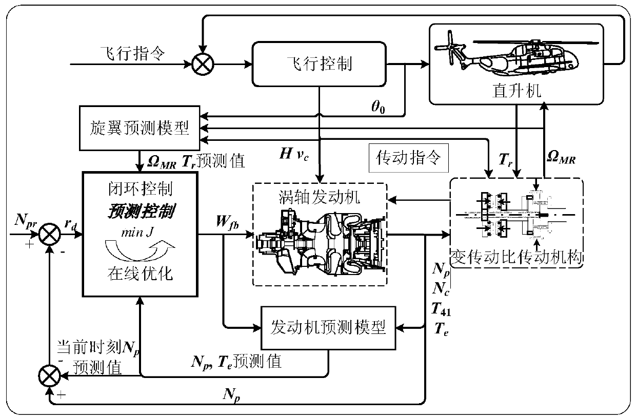
[0039] Such as figure 1 As shown, the variable rotor speed helicopter-turboshaft engine integrated control device in this embodiment is composed of three parts: a helicopter rotor prediction model, a turboshaft engine prediction model, and an online optimization unit. Both the turboshaft engine prediction model and the helicopter rotor prediction model are obtained offline. by figure 1 It can be seen that within a single simulation step, the turboshaft engine prediction model and the helicopter rotor prediction model respectively predict the output at the future time based on the input and pass it to the nonlinear model prediction controller (that is, the online optimization unit). The sequential quadratic programming (SQP) algorithm solves the objective function online, outputs the fuel control quantity, and co...


PUM


Abstract

The invention discloses a variable rotor speed helicopter-vortex engine integrated control method. The variable rotor speed helicopter-vortex engine integrated control method is characterized in thaton-line optimization of fuel flow rate of a turboshaft engine is carried out on the basis of comprehensive consideration of a speed control index and rotor dynamic characteristics of matching torque through a variable transmission ratio transmission mechanism; under the conditions of satisfying various restrictions such as compressor speed and engine static strength, speed overshoot and sag of a power turbine in the process of variable rotor speed can be significantly reduced, and not only is fast response control of the turboshaft engine realized, but also the service life of the engine is prolonged. Further disclosed is a variable rotor speed helicopter-vortex engine integrated control device. The variable rotor speed helicopter-vortex engine integrated control method and the device thereof have the advantages of significantly reducing the speed overshoot and sag of the power turbine in the process of the variable rotor speed under the conditions of satisfying the various restrictions such as compressor speed and engine static strength, realizing the fast response control of the turboshaft engine, and prolonging the service life of the engine.

Description

Technical field [0001] The invention relates to a comprehensive control method for a helicopter-turboshaft engine with variable rotor speed, and belongs to the technical field of system control and simulation in aerospace propulsion theory and engineering. Background technique [0002] The variable rotor speed helicopter has developed rapidly since its inception. Relying on its superior air combat capabilities such as superior offensiveness, maneuverability, surprise, concealment, and sensitivity, the application field and performance requirements have been continuously expanded, and the flight missions performed have also developed diversified. The tasks undertaken have gradually evolved from the past support functions such as search and rescue and material transportation to reconnaissance aircraft and ground attack functions (see [Smith B J, Zagranski R.D. Next Generation Control System for Helicopter Engines [C]]). [0003] When the rotation speed of the rotor is changed, the v...

Claims


Application Information

Patent Timeline
Patent Type & Authority Patents(China)
IPC IPC(8): B64D31/00G06F30/15G06F30/20
Inventor 汪勇郑前钢席志华高远张海波
Owner NANJING UNIV OF AERONAUTICS & ASTRONAUTICS
Learn More