Pump head and bottle body with pump head

A pump head and pump body technology, applied in the field of pump head and the bottle with the pump head, can solve the problems of bacterial infection, easy leakage of liquid, contamination of liquid in the bottle, etc., to prevent bacterial infection, prevent liquid leakage, The effect of enhancing the sealing effect

Pending Publication Date: 2019-06-18
广东美妆优品科技有限责任公司
View PDF9 Cites 3 Cited by
  • Summary
  • Abstract
  • Description
  • Claims
  • Application Information

AI Technical Summary

Problems solved by technology

[0002] Existing cosmetic liquid or toiletry products containment devices generally include a bottle body and a cover body that is sealed with the bottle body. When in use, the cover body needs to be opened, and then the cosmetic liquid is poured out, so it is difficult to avoid waste when pouring, so , a bottle body with a pump head appeared on the market. The pump head is connected to the bottle body through threads. The connection of the bottle is not sealed enough, and the liquid in the bottle is easy to leak out when the bottle is placed upside down. In order to solve this technical problem, a gasket is added at the connection between the pump head and the bottle to strengthen the seal. When the side wall of the bottle mouth is thin, the gasket is easy to shift or fall into the bottle body, so that the sealing effect is not good or the liquid in the bottle is polluted, and when the user uses the bottle body in the prior art, when the remaining liquid cannot pass through When the pump head is pumped out and the user needs to unscrew the cover to pour out, the gasket needs to be removed and placed on the table, which will cause the gasket to be stained with dust or infected by bacteria

Method used


Image

  • Pump head and bottle body with pump head
  • Pump head and bottle body with pump head
  • Pump head and bottle body with pump head

Examples


Embodiment Construction

[0020] In order for those skilled in the art to more clearly understand the purpose, technical solutions and advantages of the present invention, the present invention will be further described below with reference to the accompanying drawings and embodiments.

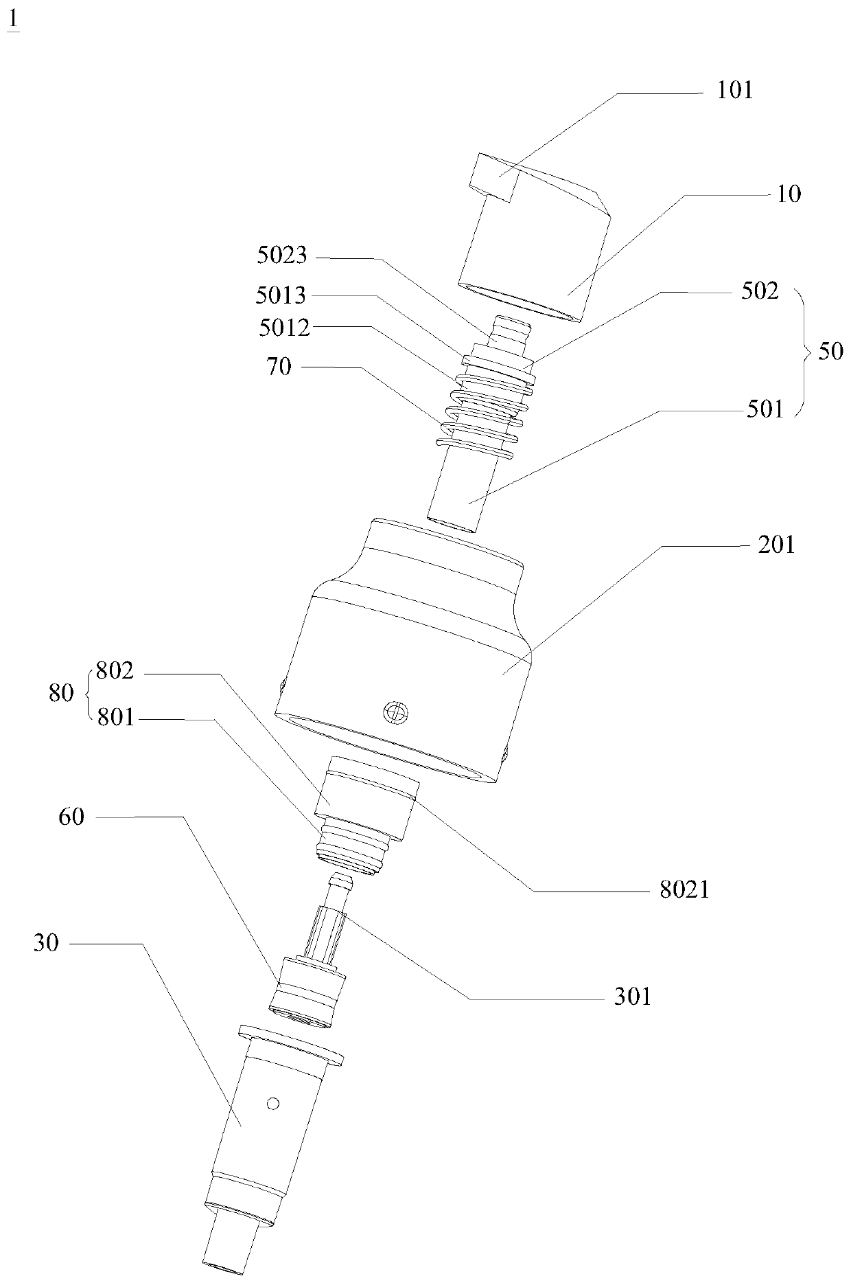
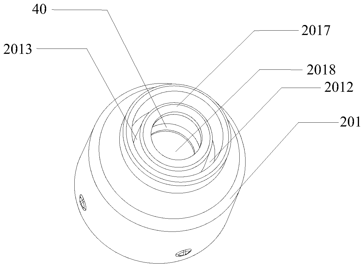
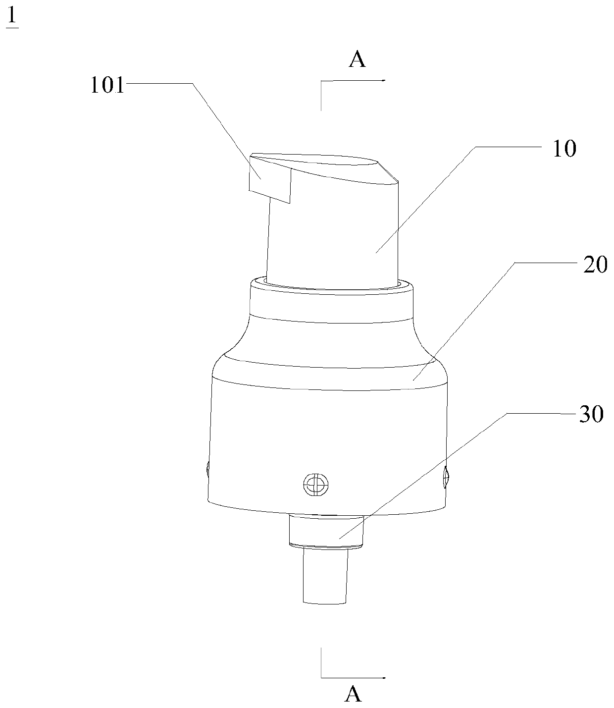
[0021] refer to Figure 1 to Figure 4 , Figure 1 to Figure 4 A specific embodiment of the pump head 1 of the present invention is shown. In the embodiment shown in the drawings, the pump head 1 includes a pressing head 10, a tooth cover 20 and a pump body 30 arranged in sequence from top to bottom, wherein the inner end of the tooth cover 20 is provided with a first installation At position 2011, a gasket 40 is fixed in the first installation position 2011. The gasket 40 is made of elastic material. The gasket 40 and the tooth cover 20 are integrally molded by a two-color injection molding machine. The elastic material can be silica gel or soft glue, etc. The pump body 30 is installed in the tooth cover 20 , which p...


PUM


Abstract

The invention discloses a pump head. The pump head comprises a pressing head, a tooth cover and a pump body arranged in sequence from top to bottom, wherein a first mounting position is arranged at the inner end of the tooth cover; a gasket is fixed in the first mounting position, and is made of an elastic material; the gasket and the tooth cover are integrally molded through injection molding bya bicolor injection molding machine; the pump body penetrates through the gasket, and the tail end extends out of the tooth cover; a pump core is arranged in the pump body, and a valve is arranged inthe tail end; the pump core is slidingly connected with a piston; a connecting piece sleeves the pump core; a return spring is clamped between the connecting piece and the pump body; and the connecting piece communicates with a liquid outlet mouth of the pressing head for pumping out liquid. The gasket and the tooth cover are integrally molded through injection molding by the bicolor injection molding machine, so that the gasket is tightly pressed between the tooth cover and a bottle opening of a bottle body when the tooth cover is connected with the bottle opening of the bottle body without easily displacing, the sealing effect during connecting between the tooth cover and the bottle body is improved, and the leakage of liquid from the bottle body can be prevented.

Description

technical field [0001] The invention relates to a liquid outlet device for cosmetics and toiletries, and more particularly to a pump head and a bottle body with the pump head. Background technique [0002] Existing cosmetic liquid or toiletries containment devices generally include a bottle body and a cover body sealingly matched with the bottle body. The cover body needs to be opened during use, and then the cosmetic liquid is poured out, which is difficult to avoid waste during pouring. , There is a bottle body with a pump head on the market. The pump head is connected to the bottle body through a thread. When the pump head is manually pressed, the liquid in the bottle is sucked by air pressure and pumped out through the head mouth of the pump head. However, the pump head and The connection of the bottle body is not sealed enough, and the liquid in the bottle body is easy to leak when the bottle body is poured. In order to solve this technical problem, a gasket is added at...

Claims


Application Information

Patent Timeline
Patent Type & Authority Applications(China)
IPC IPC(8): B65D47/34B05B11/00
CPCB05B11/1047B05B11/1023B05B11/1074
Inventor 陈岳瑜
Owner 广东美妆优品科技有限责任公司
Why Eureka
Try Eureka