Raft built-in dewatering structure, sealing-well structure of dewatering well and sealing-well method

A built-in, raft technology, applied in the direction of basic structure engineering, construction, etc., can solve the problems of not being able to pour concrete on the bottom slab in time, waterproofing of the bottom slab cushion, and damage to the protective layer due to closure, so as to achieve satisfactory stability and avoid secondary The effect of blocking

Pending Publication Date: 2019-06-18
CHINA CONSTR FIRST GRP THE SECOND CONSTR +1
View PDF0 Cites 7 Cited by
  • Summary
  • Abstract
  • Description
  • Claims
  • Application Information

AI Technical Summary

Problems solved by technology

[0006] The purpose of the present invention is to provide a raft built-in dewatering structure, a well sealing structure and a well sealing method for a dewatering well, so as to solve the problem of setting up a dewatering well at a local water accumulation position, sealing the bottom plate before concrete pouring, and then carrying out the bottom plate construction If the surface water level is high and the water volume is large, there will be a technical problem that the bottom slab concrete cannot be poured in time when it is closed, resulting in the technical problem that the bottom slab cushion, waterproof and protective layer will be damaged due to the buoyancy of the groundwater due to the closure.

Method used


Image

  • Raft built-in dewatering structure, sealing-well structure of dewatering well and sealing-well method
  • Raft built-in dewatering structure, sealing-well structure of dewatering well and sealing-well method
  • Raft built-in dewatering structure, sealing-well structure of dewatering well and sealing-well method

Examples


Embodiment Construction

[0046] In order to make the technical means, innovative features, goals and effects achieved by the present invention easy to understand, the present invention will be further described below.

[0047] The examples described here are specific specific implementations of the present invention, and are used to illustrate the concept of the present invention. They are all explanatory and exemplary, and should not be construed as limiting the implementation of the present invention and the scope of the present invention. In addition to the embodiments described here, those skilled in the art can also adopt other obvious technical solutions based on the claims of the application and the contents disclosed in the description, and these technical solutions include adopting any obvious changes made to the embodiments described here. Replacement and modified technical solutions.

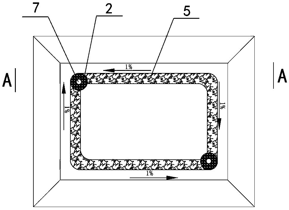
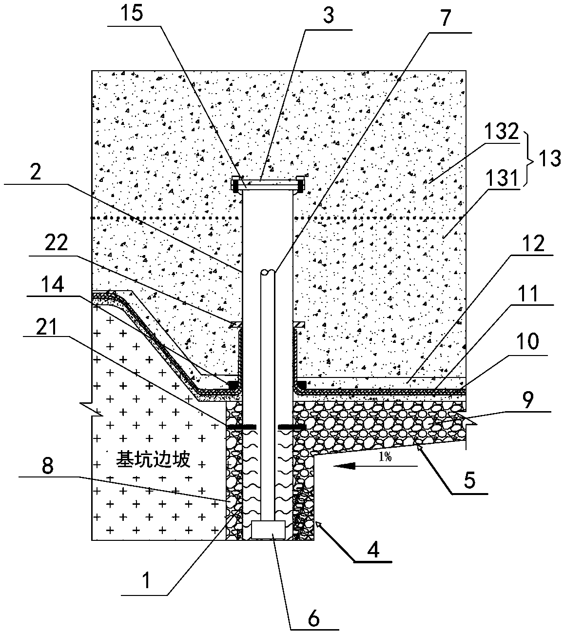
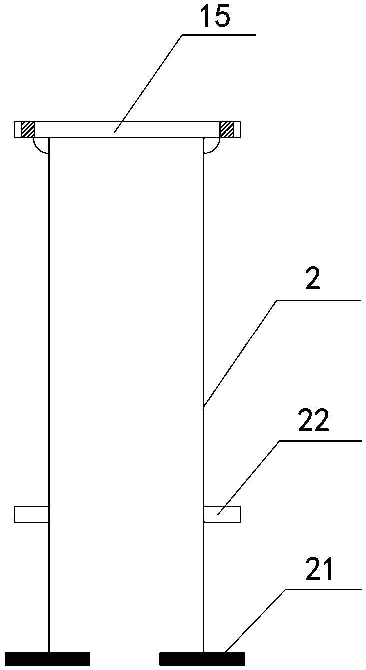
[0048] Such as Figure 1~3 As shown, a raft built-in dewatering structure is arranged at the bottom of th...


PUM


Abstract

The invention discloses a raft built-in dewatering structure, a sealing-well structure of a dewatering well and a sealing-well method, and relates to the technical field of the building construction.The raft built-in dewatering structure is arranged at the bottom of a foundation pit, and comprises a drainage ditch, a water collection pit, a well pipe, a water pump, an outer drainage pipe and electric wires, wherein the well pipe comprises a sand-free filter pipe and a water guide pipe, the sand-free filter pipe is embedded in the water collection pit, the top of the sand-free filter pipe is lower than the upper surface of the drainage ditch, the water guide pipe is arranged on the top of the sand-free filter pipe, the top of the water guide pipe exceeds the upper surface of the drainage ditch, and the top of the water guide pipe is provided with a cover plate in a covered mode. According to the raft built-in dewatering structure, the technical problems that the dewatering well is arranged at a local ponding position, sealing is conducted before concrete pouring of a base plate, then the base plate construction is conducted, if the surface water level is high and the water volume is large, the concrete pouring can not be conducted in time when sealing is conducted, resulting in a base plate cushion layer and a waterproof and protective layer being buoyed by the buoyancy of groundwater due to sealing, thus the base plate cushion and the waterproof and protective layer are destroyed are solved.

Description

technical field [0001] The invention relates to the technical field of building construction, in particular to a raft built-in dewatering structure, a dewatering well sealing structure and a well sealing method. Background technique [0002] With the continuous development of technology in the field of construction, buildings have far exceeded the range that traditional construction technology can carry no matter in terms of the height of the upward extension or the depth of the downward extension. As buildings are buried deeper and deeper, the elevation of the corresponding rafts at the bottom of the building is also lower and lower, even lower than the elevation of the surface water layer. Due to the influence of the surrounding environment, many projects are faced with water in the foundation pit. Operation. [0003] Traditional foundation pit dewatering measures mostly adopt water-stop curtains around the foundation pit and set up dewatering wells outside the water-stop...

Claims


Application Information

Patent Timeline
Patent Type & Authority Applications(China)
IPC IPC(8): E02D19/06E02D19/10
Inventor 鲍喜臣季文君刘金龙郭瑞敏李士军刘鹏梁旭
Owner CHINA CONSTR FIRST GRP THE SECOND CONSTR
Why Eureka
Try Eureka