Prefabricated building

A prefabricated and architectural technology, applied in the direction of architecture, building components, building structures, etc., can solve the problems that the construction efficiency cannot meet the requirements of prefabricated buildings, and achieve the effects of increasing construction difficulty and construction costs, saving space, and optimizing space layout

Pending Publication Date: 2019-06-18
CHINA ARCHITECTURE DESIGN & RES GRP CO LTD
View PDF0 Cites 2 Cited by
  • Summary
  • Abstract
  • Description
  • Claims
  • Application Information

AI Technical Summary

Problems solved by technology

[0004] Therefore, the present invention aims to provide a prefabricated building, which solves the problem that the construction perio

Method used


Image

  • Prefabricated building
  • Prefabricated building
  • Prefabricated building

Examples


Example Embodiment

[0046] Example 1

[0047] This embodiment provides a prefabricated building, which includes
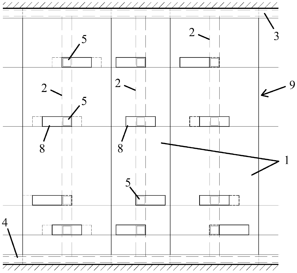
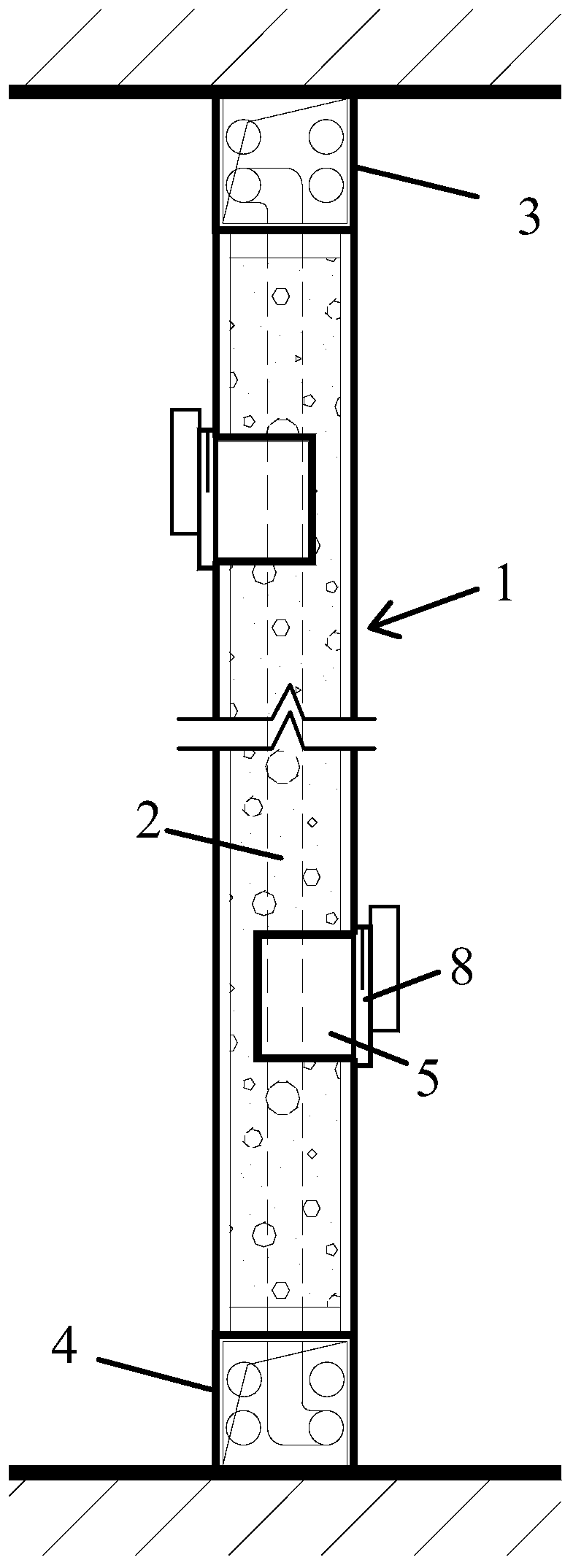
[0048] Fabricated wall panels, such as figure 1 with figure 2 As shown, it includes: a plurality of fabricated wall members 1 with at least one reserved channel 2 through which a power supply line passes, and the upper and lower ends of the reserved channel 2 respectively extend to the house The roof and the ground are respectively connected to the upper pipeline channel 3 located on the roof and the lower pipeline channel 4 located on the ground. The reserved channel 2 is arranged in the length direction extending to the fabricated wall member 1 At least one external power point interface 5, when the fabricated wall component is manufactured, a reserved channel for the power supply pipeline is reserved inside it, and a power point is reserved on the fabricated wall component Interface 5, the above reserved channel connects the upper pipeline channel and the lower pipeline channel, there...

Example Embodiment

[0059] Example 2

[0060] The difference between this embodiment and embodiment 1 is that this embodiment provides a fabricated wall member 1, such as Picture 11 As shown, the connecting surfaces of the two adjacent prefabricated wall members 1 are flat, and a plurality of prefabricated wall members 1 are connected to each other through a flat opening 5. The frame 24 is arranged at the center of the fabricated wall member 1 in the thickness direction. Thus, the force of the fabricated wall member 1 is uniform, and the strength of the fabricated wall member 1 is further improved. Moreover, the frame 24 is set at the center of the thickness direction of the fabricated wall member 1, and the fillers on both sides of the frame 24 of the fabricated wall member 1 can be made the same to ensure that the fabricated wall member 1 The strength of the connection between.


PUM


Abstract

The invention discloses a prefabricated building. The prefabricated building comprises a prefabricated wall plate, a standard ceiling and a standard ground module. A prefabricated wall body componentis internally provided with a reserved passageway allowing a power supply pipeline to penetrate through, the upper end and the lower end of the reserved passageway extend to the roof and the ground surface of a room, and communicate with an upper part pipeline passageway located on the roof and an lower part pipeline passageway located on the ground correspondingly, a power point location interface which extends to the outer part of the prefabricated wall body component is distributed in the length direction of the reserved passageway; the standard ceiling is installed on the prefabricated wall plate and comprises an connector assembly and a ceiling; the standard ground module comprises foot margins arranged on a base plane, horizontal connecting rods which are fixedly connected with the foot margins and are horizontally arranged, and a standard module, wherein the standard module is a prefabricated integrated standard module, fixedly installed on the horizontal connecting rods, and isthe main body of the ground. The problems that in the prior art, the construction period of the prefabricated building is long, and the construction efficiency still cannot meet the requirements of the prefabricated building are solved.

Description

technical field [0001] The invention relates to the technical field of prefabricated buildings, in particular to a prefabricated building. Background technique [0002] Prefabricated buildings refer to buildings assembled from prefabricated components on site. A large number of building parts of the prefabricated building are produced and processed by the workshop, and the assembly operation is carried out at the construction site. Compared with the original cast-in-place operation, the production efficiency is greatly improved, and the corresponding component cost is reduced. Prefabricated buildings not only meet the requirements of green buildings, but also effectively reduce the construction cost of the entire building. [0003] The prefabricated buildings in the prior art are constructed in the way of standardized modular walls. This kind of wall is prefabricated in the factory and installed on site. During installation, the walls are arranged and fixed. This method is ...

Claims


Application Information

Patent Timeline
IPC IPC(8): E04C2/52E04B9/30E04B1/00E04F15/024E04B2/74E04B2/82E04B1/61
Inventor 王凌云赵钿潘悦陈敬思
Owner CHINA ARCHITECTURE DESIGN & RES GRP CO LTD
Why Eureka
Try Eureka