
Two-stage compression adjustable dryness refrigeration system with ejector

A two-stage compression and refrigeration system technology, applied in refrigerators, compressors, refrigeration components, etc., can solve the problems of low condensation efficiency of condensers, unfavorable equipment miniaturization, and low heat exchange efficiency, achieving simple structure and easy maintenance , Energy-saving and material-saving effect of space occupation

Pending Publication Date: 2019-06-18
ZHONGKAI UNIV OF AGRI & ENG
View PDF0 Cites 0 Cited by
  • Summary
  • Abstract
  • Description
  • Claims
  • Application Information

AI Technical Summary

Problems solved by technology

In the traditional two-stage compression refrigeration system, if you want to increase the system efficiency or cooling capacity of the refrigeration cycle, the usual method is to increase the heat exchange area of ​​the evaporator and condenser, thereby improving the energy exchange efficiency, but it will significantly increase the material consumption and not Conducive to miniaturization of equipment
In addition, during the condensation process, steam often condenses into condensate on the wall of the condenser and spreads into a liquid film, but the thermal conductivity of the liquid film is poor, which seriously affects the transfer of heat, making the condensation efficiency of the condenser relatively low; During the evaporation process, due to the slow flow rate and low heat transfer coefficient of the heat exchange tube in the low dryness evaporation process, the heat transfer efficiency of the traditional evaporator is not high in the low dryness area. However, when the fluid is in the high dryness core In the state boiling zone, the evaporation heat transfer efficiency is significantly improved

Method used


Image

  • Two-stage compression adjustable dryness refrigeration system with ejector
  • Two-stage compression adjustable dryness refrigeration system with ejector
  • Two-stage compression adjustable dryness refrigeration system with ejector

Examples


Embodiment Construction

[0022] The present invention will be further described below in conjunction with the accompanying drawings and embodiments.

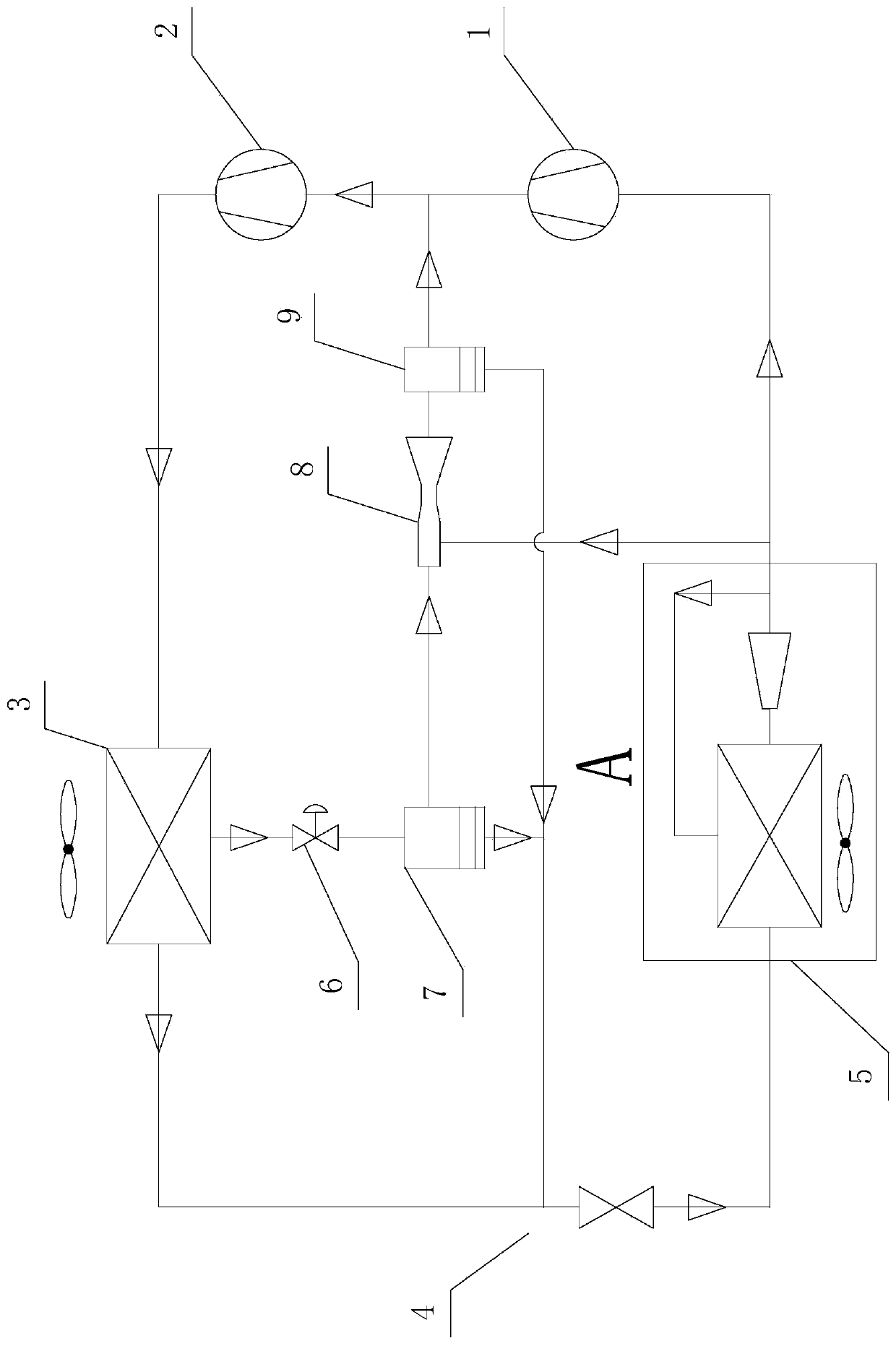
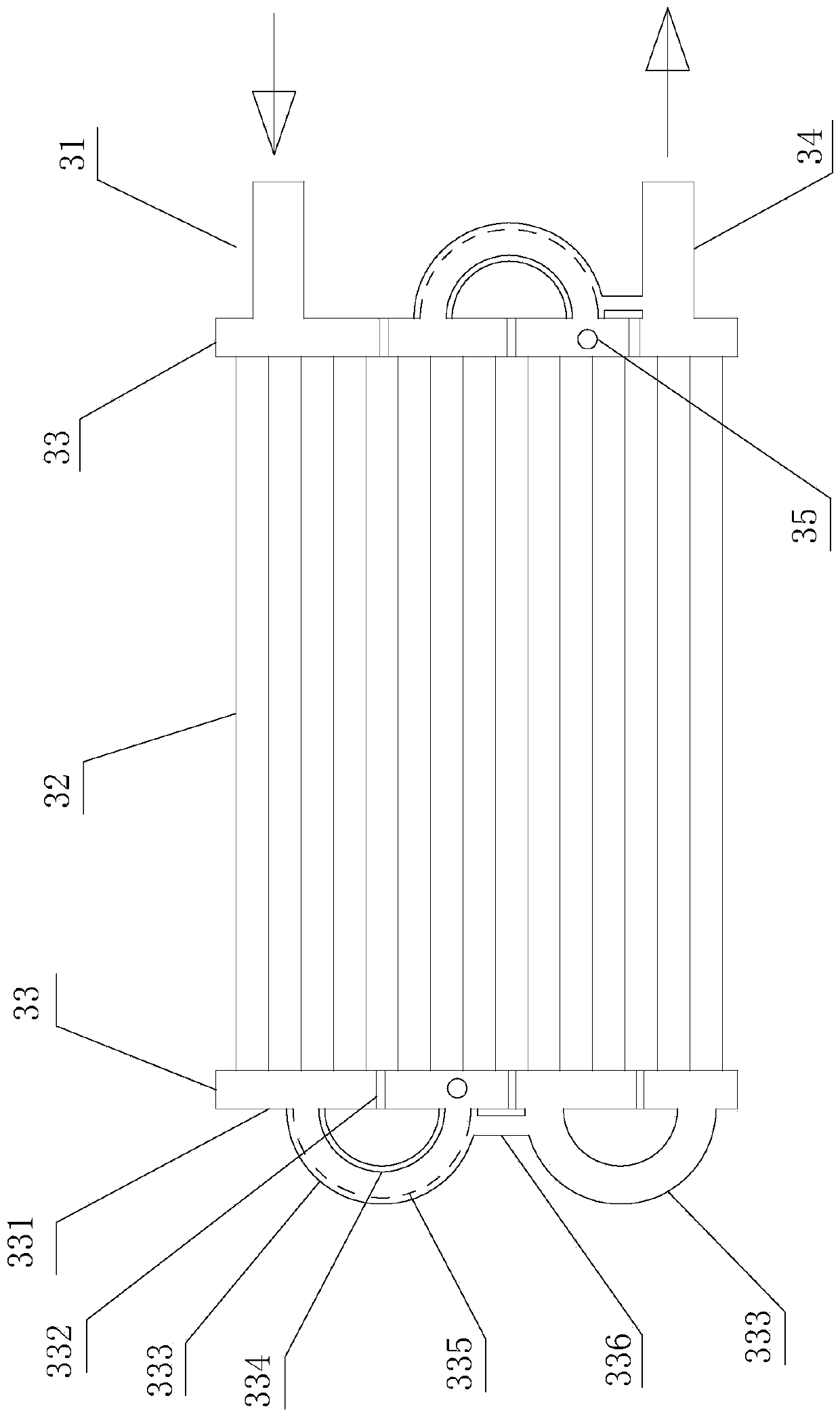
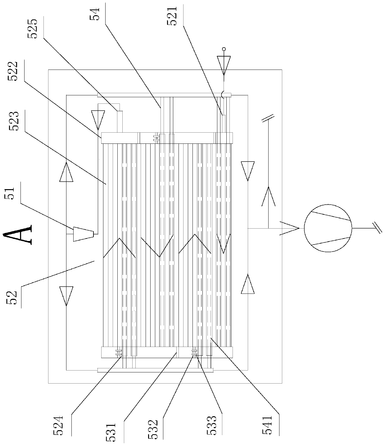
[0023] see Figure 1-Figure 4 , the two-stage compression adjustable dryness refrigeration system with ejector, including the main refrigeration cycle and injection module, the main refrigeration cycle includes the primary compressor 1, the secondary compressor 2, and the adjustable dryness condenser connected with the inlet and outlet in sequence Device 3, throttle valve 4, dryness adjustable evaporator device 5; the injection module includes an electronic valve 6, a gas-liquid separator I7, an injector 8 and a gas-liquid separator II9, wherein the inlet of the electronic valve 6 is connected to the The outlet of the dryness-adjustable condenser device 3 is connected, the outlet of the electronic valve 6 is connected with the inlet of the gas-liquid separator I7, and the outlet of the gas-liquid separator I7 is respectively connected with the outlet of...


PUM


Abstract

The invention relates to a two-stage compression adjustable dryness refrigeration system with an ejector. The two-stage compression adjustable dryness refrigeration system comprises a main refrigeration cycle and an injection module, the main refrigeration cycle comprises a primary compressor, a secondary compressor, a dryness adjustable condenser device, a throttling valve and a dryness adjustable evaporator device which communicate with each other in sequence; and the injection module comprises an electronic valve, a gas-liquid separator I, the ejector and a gas-liquid separator II. By meansof the improvement of the above structure, the shortcomings that a two-stage compression intercooling refrigeration system in the prior art has liquid film accumulation in the condensation process, is low in condensation heat transfer efficiency, is low in evaporation efficiency in the low dryness region in the evaporation process and is not high in intermediate cooling efficiency, and consequently the refrigerating cycle is low in overall energy efficiency, consumes materials and is large in occupation space of heat exchange equipment are overcome. The two-stage compression adjustable dryness refrigeration system has the characteristics of being simple in structure, higher in heat exchange efficiency, easy and convenient to maintain, capable of saving energy and materials, small in occupied space and the like, and practicality is high.

Description

technical field [0001] The invention relates to the field of refrigeration systems, in particular to a two-stage compression adjustable dryness refrigeration system with an ejector. Background technique [0002] The traditional two-stage compression refrigeration system is mainly composed of two compressors, a condenser, an evaporator and an intercooler and other components. In the traditional two-stage compression refrigeration system, if you want to increase the system efficiency or cooling capacity of the refrigeration cycle, the usual method is to increase the heat exchange area of ​​the evaporator and condenser, thereby improving the energy exchange efficiency, but it will significantly increase the material consumption and not Conducive to miniaturization of equipment. In addition, during the condensation process, steam often condenses into condensate on the wall of the condenser and spreads into a liquid film, but the thermal conductivity of the liquid film is poor, ...

Claims


Application Information

Patent Timeline
Patent Type & Authority Applications(China)
IPC IPC(8): F25B9/08F25B49/02
Inventor 钟天明丁力行陈嘉澍张平湖吕金虎卓献荣陈姝刘少达李金成
Owner ZHONGKAI UNIV OF AGRI & ENG
Learn More