Automatic LED aging state detection and service life evaluation system and method thereof

A technology of life evaluation and automatic detection, which is applied in the field of detection, can solve the problems of difficult maintenance of LED sample parts and the inability to predict the life of LED samples.

Inactive Publication Date: 2019-06-18
SUZHOU UNIV OF SCI & TECH
View PDF6 Cites 6 Cited by
  • Summary
  • Abstract
  • Description
  • Claims
  • Application Information

AI Technical Summary

Problems solved by technology

[0006] The purpose of the present invention is to provide a system for automatic detection and life evaluation of LED aging state and a method for automatic detection and life evaluation of LED aging state, so as to solve the probl

Method used


Image

  • Automatic LED aging state detection and service life evaluation system and method thereof
  • Automatic LED aging state detection and service life evaluation system and method thereof
  • Automatic LED aging state detection and service life evaluation system and method thereof

Examples


Embodiment 1

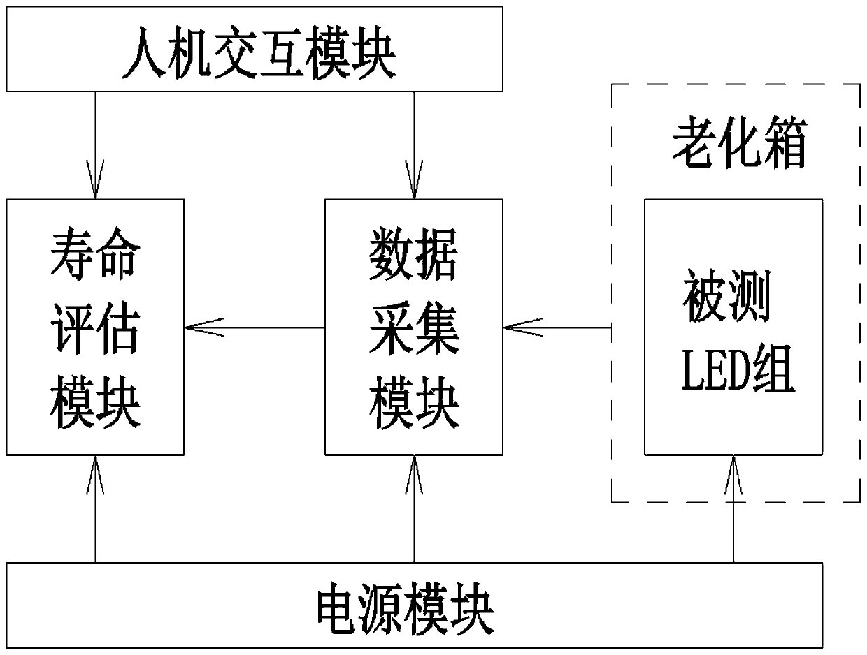
[0061] Such as figure 1 Shown is the system diagram of the LED aging state automatic detection and life evaluation system according to the exemplary embodiment of the present invention;

[0062] In this embodiment, an automatic LED aging state detection and life evaluation system is used for collecting characteristic parameters of LED samples and for performing life tests and life evaluation on LED samples, which is characterized in that it includes: a power supply module, an aging box , data acquisition module, human-computer interaction module, and life evaluation module;

[0063] The power supply module is a DC stabilized power supply, which is used to provide stable working power for LED samples, the aging box, the data acquisition module, the human-computer interaction module and the life evaluation module;

[0064] The aging box is used to provide the LED samples with the temperature and humidity required for the accelerated aging test, and the LED samples are placed in...

Embodiment 2

[0137] The first embodiment itself can be used as an independent system, and the second embodiment is based on the first embodiment, which involves a more complete LED aging state automatic detection and life evaluation system, and expands the following modules; therefore, the second embodiment can also be seen It is the detailed and specific application of the first embodiment.

[0138] Such as Figure 5 , a more complete LED aging state automatic detection and life evaluation system, which combines the functions of automatic collection of LED characteristic parameters and automatic control of LED tests, integrated in the same system to automatically control the test of LED samples and their characteristic parameters Acquisition and automatic detection of aging status and life assessment;

[0139] The system also includes an LED testing mechanism 1, a control module, an actuator 3, a detection module 4, a storage and printing module, and a display module. In addition to pow...


PUM


Abstract

The invention relates to an automatic LED aging state detection and service life evaluation system and a method thereof, thereby carrying out characteristic parameter collection of LED samples and carrying out service life testing and service life evaluation of LED samples. The system comprises a power supply module, an aging box, a data acquisition Module, a human-computer interaction module, anda service life evaluation module. Besides, according to the automatic LED aging state detection and service life evaluation method, an LED sample is placed in the aging box to carry out accelerated aging testing; service life test parameters of the LED sample are transmitted to the service life evaluation module; the service life evaluation module calculates average testing time of the LED samplewith the service life testing under the accelerated stress by using a probability statistics method; the service life evaluation module establishes a service life prediction model of multiple LED samples and carries out parameter estimation on the service life prediction model based on test results; and the service life evaluation module calculates the residual service lives of the type of LED samples in the batch under the actual using condition to obtain the service life of the tested LED under actual use conditions.

Description

technical field [0001] The invention belongs to the technical field of detection, and in particular relates to an LED state detection and life evaluation system and a method thereof. Background technique [0002] In the prior art, LED can convert electrical energy into light energy, which has the characteristics of high efficiency, pure light color, flexible application, and high light quality. Therefore, it is used as a light source in many photoelectric control equipment and as a signal display in electronic equipment. . [0003] However, during the use of the LED, due to the influence of the current and the external environment, it will inevitably age. The aging of the LED mainly includes the aging of the chip and the aging of the package. The aging mechanism of the chip includes the strengthening of thermomechanical stress caused by heat accumulation, the expansion of chip cracks, and the complete detachment of the chip bonding layer from the bonding surface caused by ...

Claims


Application Information

Patent Timeline
IPC IPC(8): G01R31/00G01M11/00
Inventor 石颉田昌前赵德宇董佳琦袁晨翔孔维相
Owner SUZHOU UNIV OF SCI & TECH
Why Eureka
Try Eureka