Broadband circular polarization filter antenna

A filter antenna, circular polarization technology, applied in the field of antennas of wireless communication terminals, to achieve the effect of circular polarization bandwidth expansion, reduction of structural complexity, and impedance matching bandwidth optimization.

A filter antenna, circular polarization technology, applied in the field of antennas of wireless communication terminals, to achieve the effect of circular polarization bandwidth expansion, reduction of structural complexity, and impedance matching bandwidth optimization.

CN109904609AActive Publication Date: 2019-06-18HANGZHOU DIANZI UNIV

Image

  • Broadband circular polarization filter antenna
  • Broadband circular polarization filter antenna
  • Broadband circular polarization filter antenna

Examples


Embodiment Construction

[0035] The present invention is further analyzed below in conjunction with specific examples.

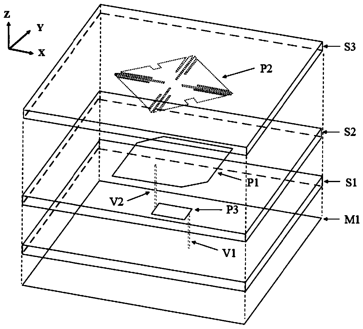
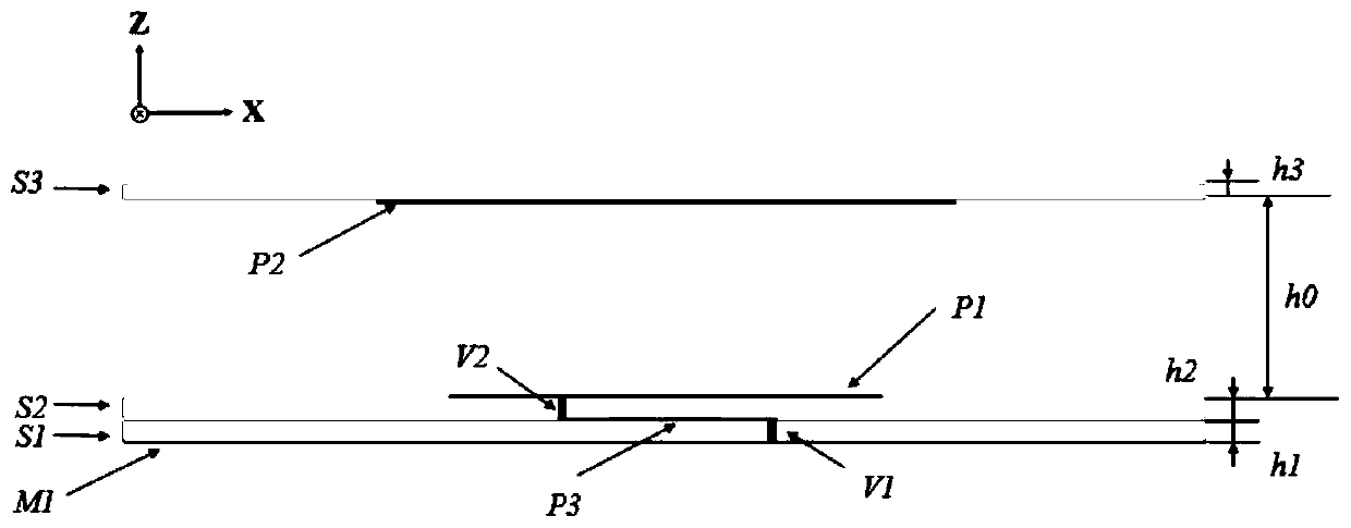
[0036] combine figure 1 with figure 2 , broadband circularly polarized filter antenna, including the first layer of Rogers5880 dielectric substrate S1 with a thickness of 1mm, the second layer of Rogers5880 dielectric substrate S2 with a thickness of 1mm, the third layer of Rogers4350 dielectric substrate S3 with a thickness of 1mm, and the same size as the dielectric substrate ground plane M1, a square cut-off radiation patch P1 with a side length of 20mm, a square slotted parasitic patch P2 with a side length of 19mm, a rectangular metal patch P3 with a length and width of 5mm and 3.5mm, and a radius of 0.2 mm metal posts V1 and V2.

[0037] The third dielectric substrate S3, the second dielectric substrate S2 and the first dielectric substrate S1 are the upper, middle and lower layers of the structure respectively. The first dielectric substrate S1 is in contact with the seco...


PUM


Abstract

The invention relates to a broadband circular polarization filter antenna. The traditional circular polarization filter microstrip antenna generally realizes the circular polarization characteristic and the filter characteristic on two structures separately, that is to say, the circular polarization characteristic is realized on a radiation patch and the filter characteristic is realized on a feedstructure, and the antenna increases the complexity of the antenna structure. The invention successfully realizes the circular polarization characteristic and the filtering characteristic on the radiation patch by utilizing a mode of directly slotting on the radiation patch, thereby greatly reducing the structural complexity. In addition, the double-layer structure of the parasitic patch loaded on the lower-layer radiation patch not only widens the S parameter, but also further expands the circular polarization bandwidth, so that the antenna meets the frequency band requirement of 5G communication.

Description

technical field [0001] The invention belongs to the technical field of antennas for wireless communication terminals, and relates to a broadband circularly polarized filter antenna, which can be used as an antenna for a radio frequency front end of a miniaturized wireless transceiver and is widely used in wireless communication systems such as mobile communication, satellite communication, and radar. Background technique [0002] With the development of modern wireless communication systems, the RF front-end structure is developing in the direction of multi-function, miniaturization and integration. As the two most important components of the RF front-end circuit, the antenna and filter, their size and performance are crucial to the quality of the overall system. The traditional design method separates the design of the antenna and the filter, which causes the loss of the two devices due to incomplete matching when cascaded. The filter antenna formed by integrating the anten...

Claims


Application Information

Patent Timeline
18 Jun 2019
Publication
CN109904609A
IPC
H01Q1/50; H01Q1/48; H01Q1/38
Inventors
罗国清; 王文磊