Permanent magnet high-speed motor, rotor magnetic steel fixing structure and pre-tightening method thereof
A high-speed motor and magnetic steel technology, which is applied in the shape/style/structure of the magnetic circuit, the rotating parts of the magnetic circuit, and the manufacture of the stator/rotor body, etc. Excessive sealing requirements, centrifugal clearance and vibration, etc., to achieve reliable preload, good cooling effect, and eliminate centrifugal clearance and vibration
- Summary
- Abstract
- Description
- Claims
- Application Information
AI Technical Summary
Problems solved by technology
Method used
Image

Examples
Embodiment 1
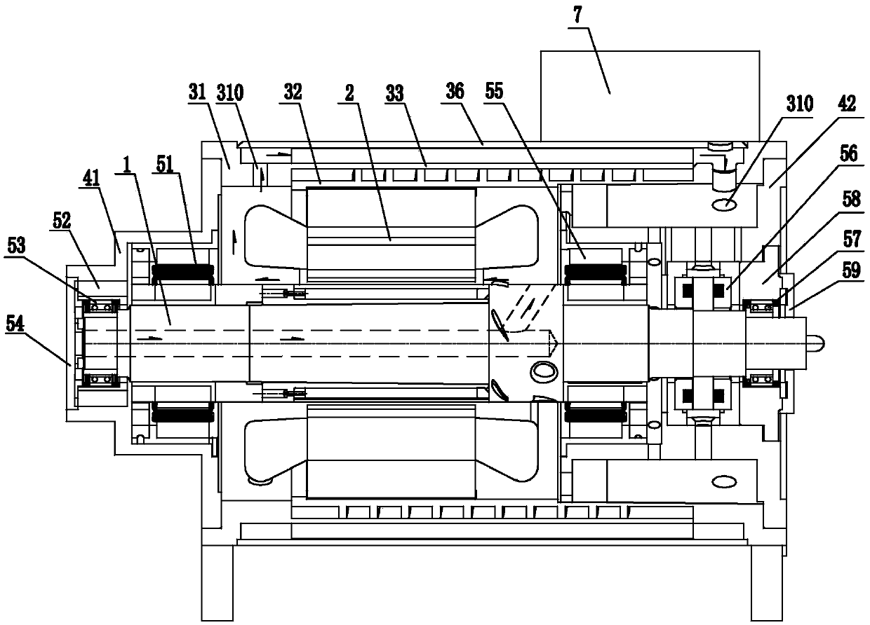
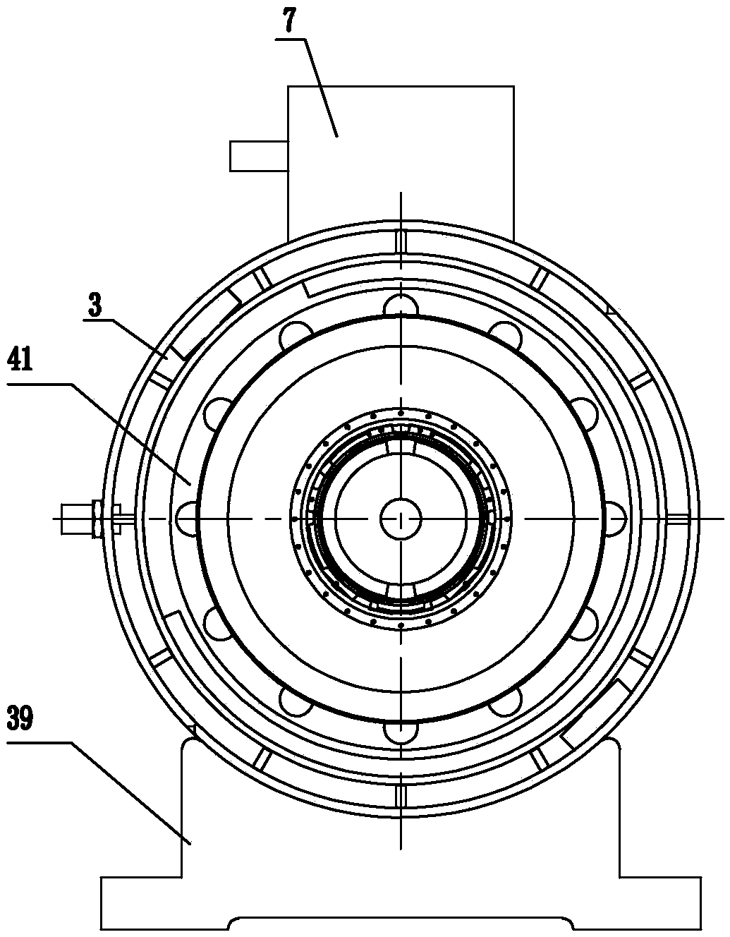
[0027] Embodiment 1, referring to Fig. 1, has shown the permanent magnet high-speed motor of the present invention among the figure, and it comprises rotor 1, stator 2, machine base 3 (or claim casing), be located at both ends non-drive end cover 41 and The driving end cover 42; wherein, the rotor 1 is arranged on the non-driving end cover 41, the driving end cover 42 and the machine base 3 through the bearing seat, and the non-driving end cover 41 is fixed on the end of the machine base 3, which includes the The cover plate connected to the seat 3 and the stepped two-part sleeve extending outward, the inner end sleeve is provided with a radial bearing 51, and the outer end sleeve is provided with a bearing seat 52 for mounting the bearing 53, A bearing cover 54 is provided outside the bearing 53; the drive end cover 42 has a sleeve part for setting the bearing, and a radial bearing 55, a thrust bearing 56 and a bearing 57 are arranged in sequence from the inside to the outside...
Embodiment 2
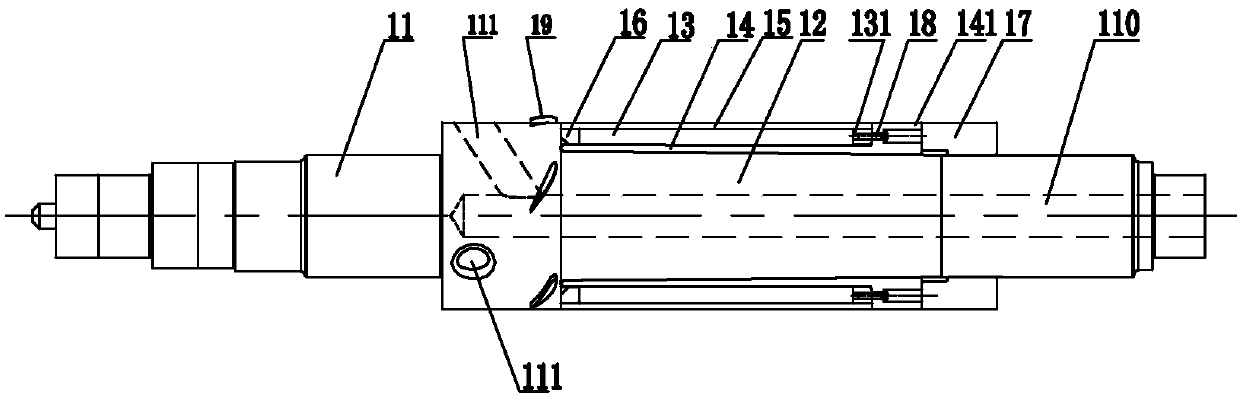
[0036] Embodiment 2, see figure 2 , the figure shows the rotor magnet fixing structure of the permanent magnet high-speed motor, which includes a rotating shaft 11, a magnetic steel 13 arranged on the surface of the rotating shaft 11, and a magnetic isolation bridge 16 between adjacent poles; Carbon fiber sleeve 15, the carbon fiber sleeve 15 is used to fix the magnetic steel 13; as described in the above embodiment, the feature of the present invention is that the rotating shaft 11 is used to set the position of the magnetic steel 13, and the tapered section 12 with a large inside and a small outside A tapered taper sleeve 14 with a tapered hole and an interference fit with the taper section 12 is arranged on the tapered section 12. At this time, the magnetic steel 13 is arranged on the outside of the wedged taper sleeve 14 On the surface, the carbon fiber sleeve 15 is located outside the magnetic steel 13 for fixing the magnetic steel; see image 3 , the end of the wedge-s...
PUM
 Abstract
Description
Claims
Application Information
 - R&D
- Intellectual Property
- Life Sciences
- Materials
- Tech Scout
- Unparalleled Data Quality
- Higher Quality Content
- 60% Fewer Hallucinations
Browse by: Latest US Patents, China's latest patents, Technical Efficacy Thesaurus, Application Domain, Technology Topic, Popular Technical Reports.
© 2025 PatSnap. All rights reserved.Legal|Privacy policy|Modern Slavery Act Transparency Statement|Sitemap|About US| Contact US: help@patsnap.com