Design method for forming an optimal weight by self-adaptive wave beams of a uniform-power broadband signal

An adaptive beam and broadband signal technology, applied in wireless communication, space transmit diversity, network planning, etc., can solve the problem of large pointing error of pattern beam pointing and adaptive interference suppression, and achieve improved interference nulling and good correction effect of effect

Active Publication Date: 2019-06-18
HARBIN INST OF TECH
View PDF5 Cites 6 Cited by
  • Summary
  • Abstract
  • Description
  • Claims
  • Application Information

AI Technical Summary

Problems solved by technology

[0005] The purpose of the present invention is to solve the problem of large errors in the beam pointing and adaptive interference suppression pointing of the pa

Method used


Image

  • Design method for forming an optimal weight by self-adaptive wave beams of a uniform-power broadband signal
  • Design method for forming an optimal weight by self-adaptive wave beams of a uniform-power broadband signal
  • Design method for forming an optimal weight by self-adaptive wave beams of a uniform-power broadband signal

Examples


specific Embodiment approach 1

[0020] Specific implementation mode 1: The specific process of the design method for the optimal weight value of the adaptive beamforming of the uniform power broadband signal in this implementation mode is as follows:

[0021] Step 1. Construct the expression of uniform power broadband signal in any array;

[0022] Step 2, applying the expression of the uniform power broadband signal in the arbitrary array in the step 1 to the uniform linear phased array to obtain the covariance matrix of the useful signal, the interference signal and the noise signal;

[0023] Step 3: Substituting the covariance matrix of useful signal, interference signal, and noise signal obtained in step 2 into the linearly constrained minimum variance criterion to obtain optimal adaptive weights.

specific Embodiment approach 2

[0024] Specific embodiment two: the difference between this embodiment and specific embodiment one is that in the step one, the expression of the uniform power broadband signal in any array is constructed; the specific process is:

[0025] Suppose the source of the uniform power broadband signal is s(t), the bandwidth of the uniform power broadband signal is B, and the center frequency of the uniform power broadband signal is f 0 , and the power spectral density of s(t) obeys the uniform distribution, that is, the power spectral density function of the signal s(t) is p s (f);

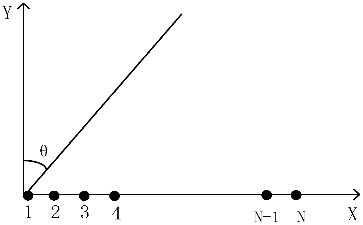
[0026] Assume that there are N array elements in an array (this array can be any array, an array of uniform power spectral density broadband signals), the first array element is located at the origin of the Cartesian coordinate system, and the coordinates of any array element in the array can be expressed as z i =(x i ,y i ),

[0027] where i=1,2,...,N,x i is the abscissa of the array element, y i...

specific Embodiment approach 3

[0044] Embodiment 3: The difference between this embodiment and Embodiment 1 or 2 is that the power spectral density function p of the signal s(t) s (f) The expression is:

[0045]

[0046] Among them, t is the time variable, p s (f) is the power spectral density function of the signal s(t), f is the frequency variable, and p is the power spectral density of the signal s(t).

[0047] Other steps and parameters are the same as those in Embodiment 1 or Embodiment 2.


PUM


Abstract

The invention discloses a design method for an adaptive beam forming optimal weight of a uniform power broadband signal, and relates to a design method for an adaptive digital beam forming optimal weight. The objective of the invention is to solve the problem of large angle error caused by the fact that wave beam pointing of wave beam forming and self-adaptive interference suppression pointing areinfluenced when the bandwidth is very large for broadband signals in the prior art. The method specifically comprises the following steps: step 1, constructing an expression of a uniform power broadband signal in any array; Step 2, applying the expression of the uniform power broadband signal in any array in the step 1 to a uniform linear phased array to obtain a covariance matrix of a useful signal, an interference signal and a noise signal; and step 3, substituting the covariance matrixes of the useful signal, the interference signal and the noise signal obtained in the step 2 into a linearconstraint minimum variance criterion to obtain an optimal adaptive weight. The method is applied to the field of broadband signal self-adaptive beam forming optimal weight design.

Description

technical field [0001] The invention relates to a design method for an adaptive digital beam forming optimal weight. Background technique [0002] Digital phased array radar perfectly combines digital technology and antenna technology, and replaces traditional analog beam forming with digital beam forming (DBF) in transmitting and receiving modes, which has advantages that traditional radars cannot match. At the same time, in order to obtain high distance resolution, high ranging accuracy, improve the radar's resolution of targets, and improve radar anti-jamming, the transmitted signal will use a signal with a large instantaneous bandwidth. If the phased array radar uses broadband signals, its functions and performance will be greatly improved. For example, the use of broadband signals in the early warning aircraft can greatly improve the anti-jamming performance of the early warning aircraft and improve the detection ability of the early warning aircraft under strong inter...

Claims


Application Information

Patent Timeline
IPC IPC(8): H04B7/06H04B7/0408H04W16/28
CPCY02D30/70
Inventor 李国宇胡航胡昊
Owner HARBIN INST OF TECH
Why Eureka
Try Eureka