

Manufacturing method of pressure-bearing equipment inner wall surfacing shell
A technology for pressure-bearing equipment and a manufacturing method, which is applied in the field of surfacing welding shells on the inner wall of pressure-bearing equipment, can solve problems such as low production efficiency, poor manufacturing quality, and high manufacturing difficulty, and achieve stable processing quality, improved product processing efficiency, The effect of improving economic efficiency
- Summary
- Abstract
- Description
- Claims
- Application Information
AI Technical Summary
Problems solved by technology
Method used
Image

Examples
specific Embodiment approach 1
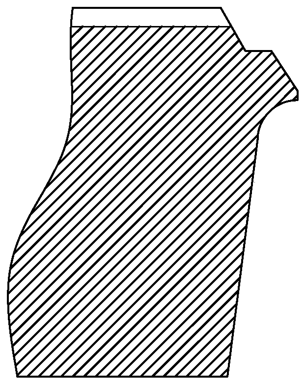
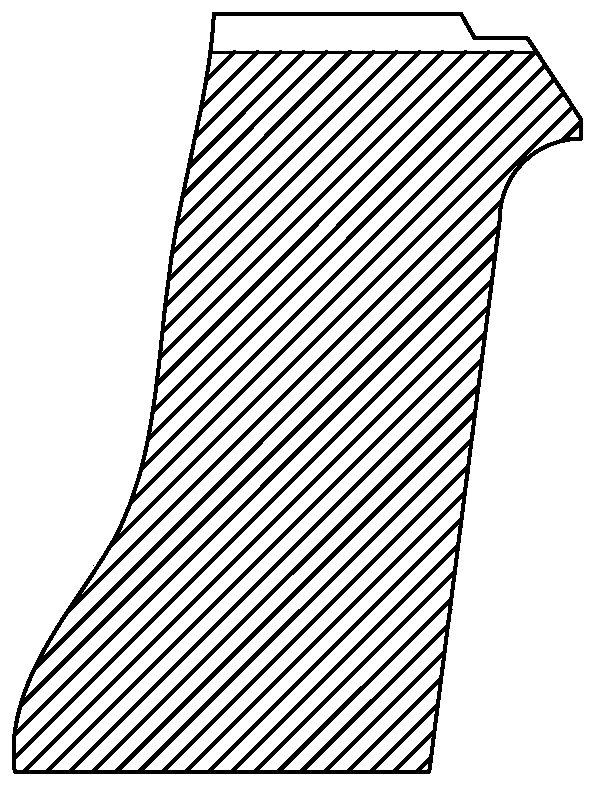
[0023] Specific implementation mode one: combine Figure 1 to Figure 8 To illustrate this embodiment, the method for manufacturing a pressure-bearing equipment inner wall surfacing shell described in this embodiment includes the following steps:
[0024] Step 1: Blanking: first re-inspect the steel plate, and then cut the material by gas cutting after the re-inspection is qualified. When cutting the material, leave a machining allowance L1 around the steel plate;
[0025] Step 2: shell forming: process the gas-cut steel plate into a pressure equipment shell 1;
[0026] Step 3: Processing of circular seam groove: first draw four centerlines and circular seam groove position line, then perform circular seam groove processing on the lathe, process circular seam inner groove 4 and circular seam outer groove 3;
[0027] Step 4: Overlay welding: Based on the inner groove 4 of the circular seam, perform surfacing welding on the pressure equipment shell 1. The overlay welding layer 2...
specific Embodiment approach 2
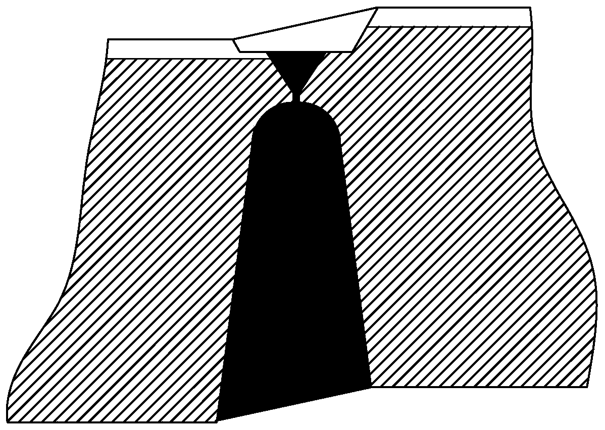
[0030] Specific implementation mode two: combination Figure 4 to Figure 5 To illustrate this embodiment, when the circular seam groove is processed in the third step of this embodiment, the inner surface of the circular seam groove can be processed with an inclined transition 5 according to the material, wall thickness, external dimension and ellipticity of the shell. The inclined transition 5 on the inner surface of the groove is performed after the inner groove 4 of the annular seam is processed, and the wall thickness at the inclined transition 5 on the inner surface of the annular seam after processing must meet the minimum design wall thickness requirement of the shell 1 of the pressure-bearing equipment. The undisclosed technical features in this embodiment are the same as those in the first embodiment.
[0031] This design is to reduce or reduce the ellipticity of the annular groove of the formed shell and the ellipticity after surfacing welding as much as possible und...
specific Embodiment approach 3
[0032] Specific implementation mode three: combination Figure 4 to Figure 5 To illustrate this embodiment, before step 3 of this embodiment processes the outer groove 3 of the annular seam, the machining allowance 6 for the outer groove of the annular seam needs to be processed. The mouth processing allowance 6 is processed, and the inner groove 4 of the annular seam is processed and trimmed. The undisclosed technical features in this embodiment are the same as those in the second embodiment.
[0033] It is designed in this way to eliminate the influence of welding shrinkage caused by surfacing welding on the machining dimensional accuracy of the shell. The size of the outer groove machining allowance 6 of the circular seam is affected by the shape of the shell, the material, the ratio of diameter and wall thickness, the thickness of the surfacing layer, Influenced by factors such as specific design and technical requirements.
PUM
| Property | Measurement | Unit |
|---|---|---|
| thickness | aaaaa | aaaaa |
Abstract
Description
Claims
Application Information