Multi-stable variable-stiffness robot structure
A technology of variable stiffness and robotics, applied in the field of robotics, can solve the problems of small stiffness adjustment range, long stiffness adjustment time-consuming, continuous and controllable stiffness adjustment, etc., and achieve the effect of simple structure, low cost, and easy realization
- Summary
- Abstract
- Description
- Claims
- Application Information
AI Technical Summary
Problems solved by technology
Method used
Image
Examples
Embodiment 1
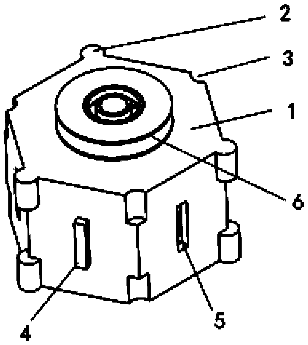
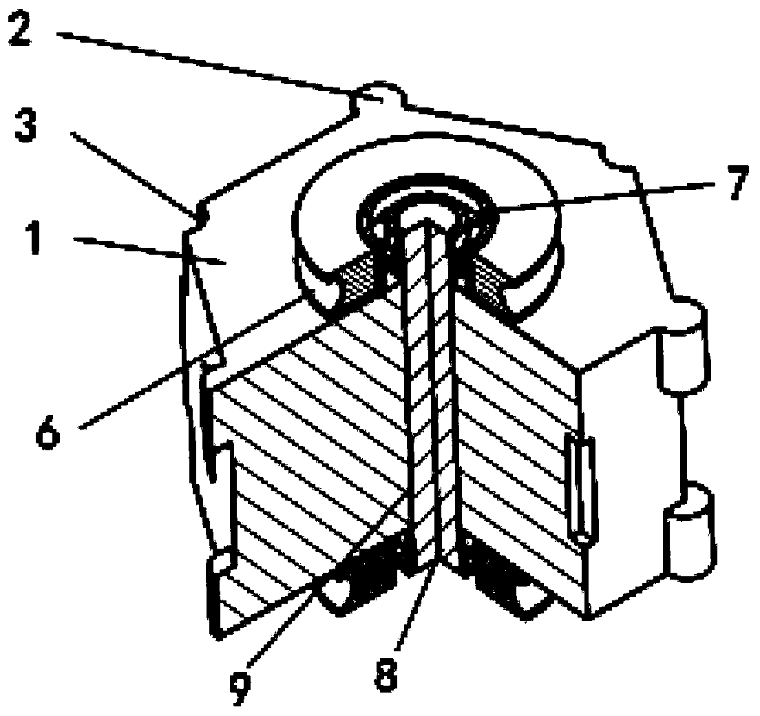
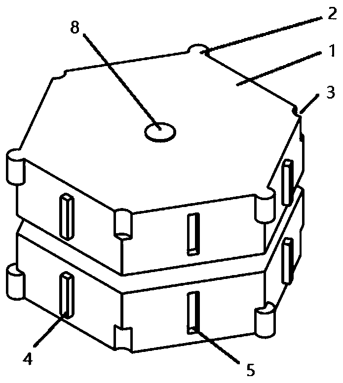
[0037] like figure 1 , Figure 2a , Figure 2b , Figure 3a and Figure 3b As shown, a multi-stable robot with variable stiffness includes at least a unit body 1, a limit shaft 2, a limit shaft groove 3, a limit block 4, a limit groove 5, a sheave 6, a bearing 7, a shaft 8, and a shaft Hole 9, rope 10, fixed end 11, movable end 12. Wherein the unit main body 1, the limiting rotating shaft 2, the limiting rotating shaft groove 3, the limiting block 4, the limiting groove 5, the sheave 6, the bearing 7, the shaft 8, and the shaft hole 9 form a basic unit. The unit main body 1 is a hexagonal block structure, and the six sides are spaced with limiting blocks 4 and limiting grooves 5, and the limiting rotating shaft 2 and the limiting rotating shaft groove 3 are distributed on six edges parallel to the axis direction of the unit main body 1 at intervals. On the side; there is a shaft hole 9 at the center line of the unit main body 1, which is interference fit with the shaft 8;...
Embodiment 2
[0043] Such as Figure 3c and Figure 3d As shown, a multi-stable variable-stiffness robot, the realization principle of its abrupt stiffness change is: move the movable end 12 to make it close to the fixed end 11, relax the rope 10, and reduce the force between the units of the multi-stable variable-stiffness robot. At this time, the multi-stable variable-stiffness robot is in a low-stiffness state, and the ability to resist external forces is weak; when the movable end 12 is far away from the fixed end 11, the rope 10 is tensioned, and the multi-stable variable-stiffness robot is in a high-stiffness state , its ability to resist external forces is greatly enhanced. The multi-stable variable stiffness robot has a short switching time between high and low stiffness states, and its stiffness can vary more than a hundred times.
[0044] The degree of tightness of the rope 10, the maximum degree of relaxation should be two adjacent units, which can be relatively rotated through...
Embodiment 3
[0046] Such as Figure 4a and Figure 4b As shown, the first end of the rope 10 passes through the lower right side through hole of the movable end 12 and the fixed end 11 successively, and winds on the sheaves 6 on the same side of each unit. When reaching the sheave 6 of the end unit, make one and a half circles, that is, the rope 10 winds in from one side of the sheave 6 of the end unit, and winds out from the symmetrical side; then winds back around the sheave 6 of the previous unit, also making a circle , and finally stretch out from the upper right side through hole of the fixed end 11 and the movable end 12. At this time, the head end of the rope 10 penetrates the movable end 12 and the upper left side of the fixed end 11 through hole again, according to the above-mentioned winding method, the other parts of each unit are One side of the sheave 6 is wound, and finally the head end of the rope 10 protrudes from the lower left through hole of the fixed end 11 and the mov...
PUM
 Abstract
Description
Claims
Application Information
 - R&D
- Intellectual Property
- Life Sciences
- Materials
- Tech Scout
- Unparalleled Data Quality
- Higher Quality Content
- 60% Fewer Hallucinations
Browse by: Latest US Patents, China's latest patents, Technical Efficacy Thesaurus, Application Domain, Technology Topic, Popular Technical Reports.
© 2025 PatSnap. All rights reserved.Legal|Privacy policy|Modern Slavery Act Transparency Statement|Sitemap|About US| Contact US: help@patsnap.com


