Stripping device used for ground dirt removal of nuclear facility
A technology for stripping devices and nuclear facilities, applied in stone processing equipment, building maintenance, stone processing tools, etc., can solve the problems of uncontrollable decontamination depth and low decontamination efficiency, achieve large working surface, reduce labor intensity, The effect of high dust collection rate
- Summary
- Abstract
- Description
- Claims
- Application Information
AI Technical Summary
Problems solved by technology
Method used
Image
Examples
Embodiment 1
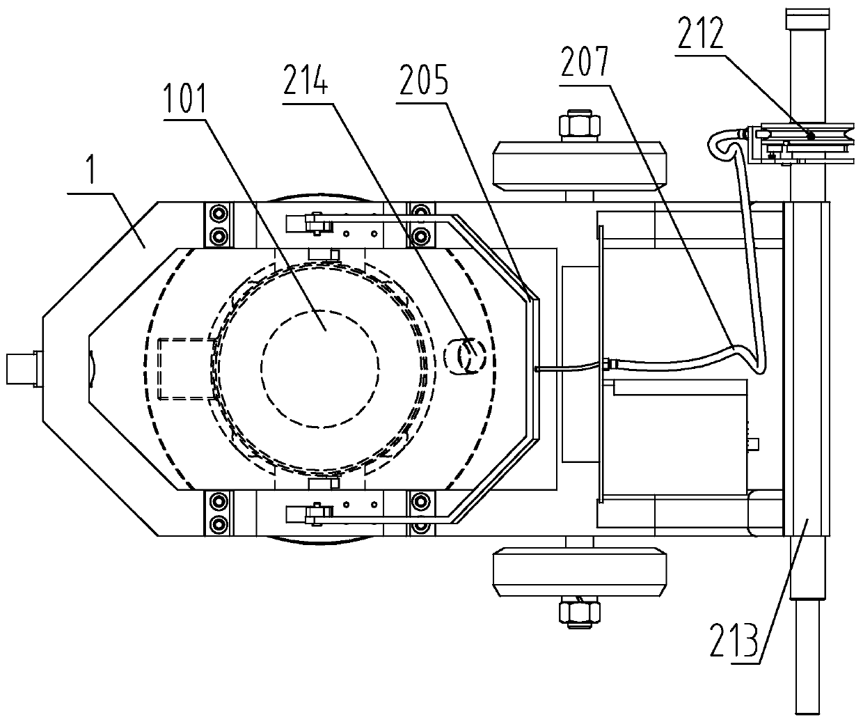
[0029] A stripping device for ground decontamination of nuclear facilities, such as figure 1 As shown, it includes a frame 1, a cutting mechanism for cutting the ground, a driving mechanism for driving the cutting mechanism to cut, and a cutterhead feeding mechanism for adjusting the cutting depth of the cutting mechanism.
[0030] Wherein, cutting mechanism is installed on the frame 1 by bearing block 105, and driving mechanism is installed on the frame 1 by supporting frame 102, is connected by coupling 103 between cutting mechanism and driving mechanism.
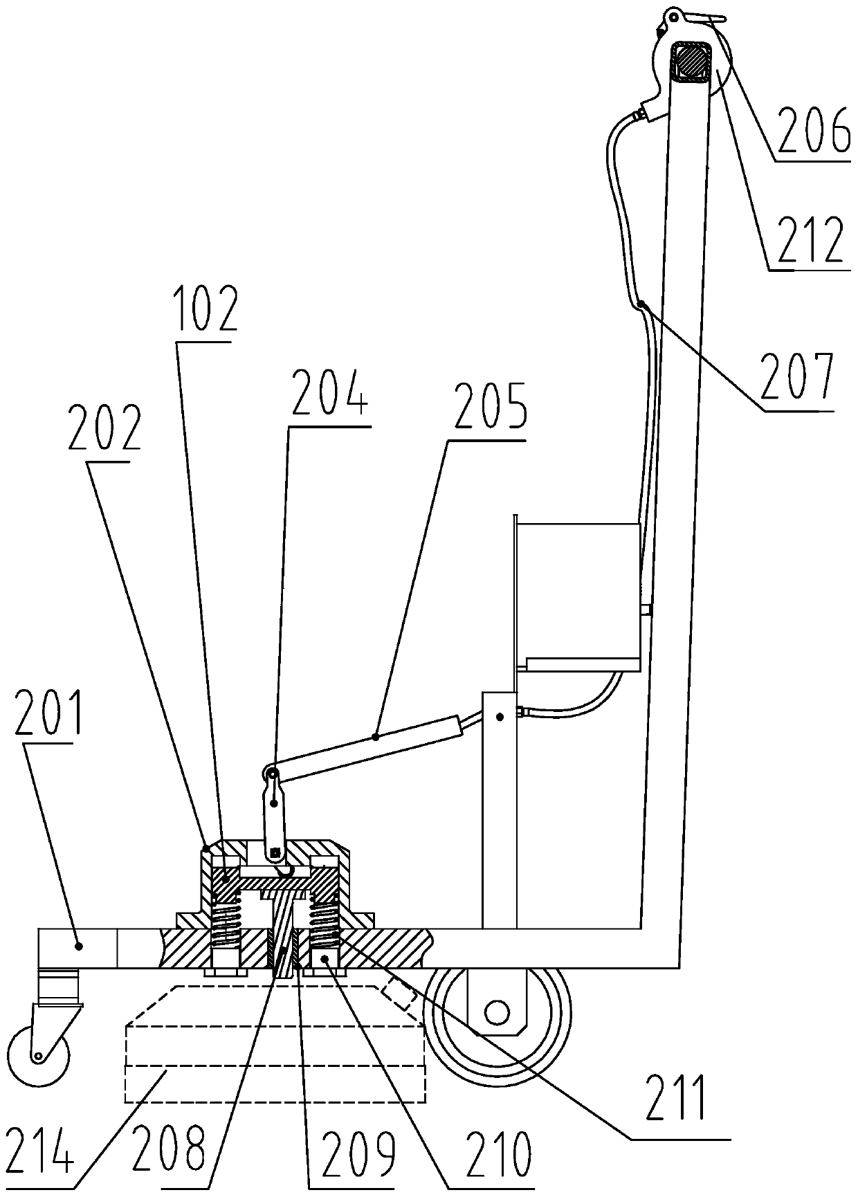
[0031] Described knife head feeding mechanism comprises the spring seat 202 that is arranged on the frame 1, the spring 211 that is installed on the spring seat 202, is arranged on the adjustment frame on the spring 211, is arranged on the spring seat 202 and is used for controlling the adjustment frame vertically. Height adjustment assembly for vertical height.
[0032] In the present invention, the adjustment frame can...
Embodiment 2
[0041] The difference between this embodiment and Embodiment 1 is that this embodiment further optimizes the structure of the height adjustment assembly on the basis of Embodiment 1, such as image 3 As shown, the specific settings are as follows:
[0042] The spring seat 202, the spring 211, the adjustment frame and the pull rod 204 are two groups, which are respectively arranged on the opposite sides of the cutting mechanism. Two pull rods 204 are hinged at the top, and the middle part of the connecting rod 205 is connected with the end of the steel wire rope 207. And, two springs 211 are arranged in each spring seat 202, four springs 211 are arranged in total, and two sides of cutting mechanism are arranged respectively, as image 3 shown. Through the setting of the above structure, the stability of height adjustment can be further improved.
[0043] At the same time, a guide shaft 208 is provided below the adjustment frame, and a position-limiting sleeve 209 that urges ...
Embodiment 3
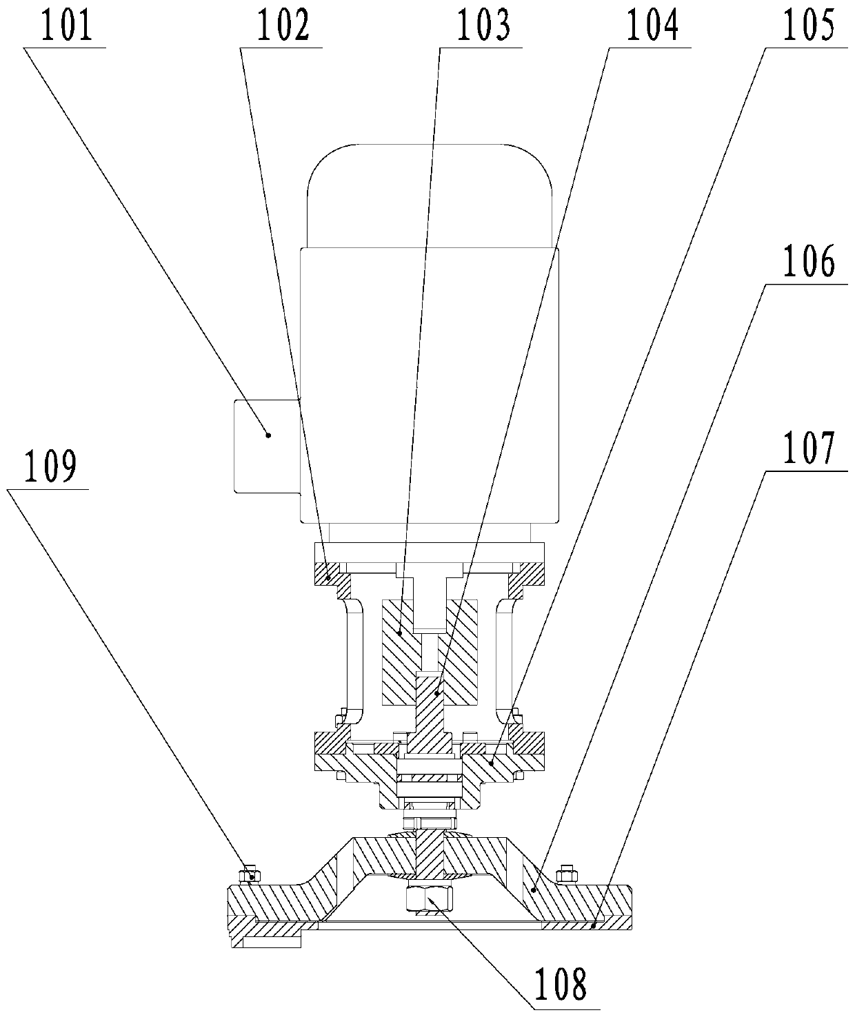
[0045] The difference between this embodiment and Embodiment 1 and Embodiment 2 is that this embodiment further provides the structure of the driving mechanism and the cutting mechanism, such as figure 2 and image 3 As shown, the specific settings are as follows:
[0046] The driving mechanism is a motor 101, and the speed is regulated by a control system frequency converter.
[0047] Described cutting mechanism comprises the main shaft 104 that the top is connected on the coupling 103, is fixed on the flywheel disc 106 of main shaft 104 bottom by bolt 108, is fixed on the cutterhead 107 on the flywheel disc 106 by set screw 109; Connected on the frame 1 through the bearing seat 105.
[0048] In this embodiment, the cutting mechanism adopts the principle of flywheel operation, and the flywheel disc 106 adopts a butterfly structure, so that after the cutter disc 107 runs at high speed under the drive of the motor 101, it can use its own inertia to perform rotary cutting ope...
PUM
 Abstract
Description
Claims
Application Information
 - R&D
- Intellectual Property
- Life Sciences
- Materials
- Tech Scout
- Unparalleled Data Quality
- Higher Quality Content
- 60% Fewer Hallucinations
Browse by: Latest US Patents, China's latest patents, Technical Efficacy Thesaurus, Application Domain, Technology Topic, Popular Technical Reports.
© 2025 PatSnap. All rights reserved.Legal|Privacy policy|Modern Slavery Act Transparency Statement|Sitemap|About US| Contact US: help@patsnap.com


