A fault diagnosis method for vehicles driven by distributed in-wheel motors

An in-wheel motor, distributed technology, applied in electric vehicles, vehicle components, electrical devices, etc., can solve the problems of sensor feedback signal distortion, vehicle loss of stability, tires unable to receive the vehicle controller in real time, etc., to ensure safety effect

Active Publication Date: 2022-05-06
WUHAN UNIV OF TECH
View PDF14 Cites 0 Cited by
  • Summary
  • Abstract
  • Description
  • Claims
  • Application Information

AI Technical Summary

Problems solved by technology

[0004] However, when the hardware in the vehicle hub motor fails, for example: the hub motor controller is damaged in the communication harness, the harness is not in good contact, the internal magnetism of the hub motor is weakened, and the sensor feedback signal is distorted.
These failures cannot be diagnosed and identified by computer equipment such as the CAN bus, and due to failures such as damage to the wiring harness, the failure signal cannot be transmitted to the vehicle controller through the communication harness. Such failures are difficult to be detected by common fault diagnosis techniques , so it has become an urgent problem to be solved in vehicle fault diagnosis at the present stage
Due to the occurrence of failure faults, the faulty tires cannot receive the torque command from the vehicle controller in real time, resulting in a large deviation between the actual torque of the vehicle tires and the target torque, and the actual torque of each tire of the vehicle will vary. When a large mutation occurs, the vehicle will also experience instability. When the vehicle speed is high, the vehicle will lose stability and cause safety problems.

Method used


Image

  • A fault diagnosis method for vehicles driven by distributed in-wheel motors
  • A fault diagnosis method for vehicles driven by distributed in-wheel motors
  • A fault diagnosis method for vehicles driven by distributed in-wheel motors

Examples


Embodiment Construction

[0050] The present invention will be further described below in conjunction with specific examples and accompanying drawings.

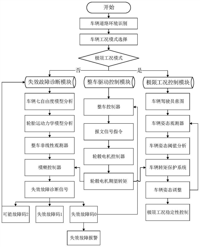
[0051] figure 1 It is the overall layout strategy diagram of the present invention. The design of the present invention uses the driver to actively judge the external environment of the vehicle, and then the vehicle controller judges the driver's intention, and then selects the working mode of the distributed in-wheel motor-driven vehicle based on the driver's judgment result, which is mainly divided into Extreme operating mode and non-extreme operating mode. The extreme working condition mode refers to the controllability of the vehicle when the vehicle is driving on low-adhesion roads (waterlogged roads, ice and snow roads, muddy roads, etc.) and stability is low, at this time the vehicle dynamics and stability state parameters are approaching the peak value, the working mode in this case is the extreme working condition mode; the non-limit working...


PUM


Abstract

The invention provides a method for diagnosing and identifying the failure of a vehicle driven by a distributed in-wheel motor. According to the movement status of the vehicle driven by a distributed in-wheel motor, the state parameters of the vehicle are obtained in real time by using the inherent sensor of the vehicle, and at the same time, a nonlinear observer for the vehicle is designed. Vehicle dynamics analysis and tire dynamics analysis to obtain the actual torque of each wheel hub motor and the expected motor torque sent by the vehicle controller; through the ratio analysis of the actual torque of each wheel hub motor and the expected motor torque, the same The ratio of the actual torque of the in-wheel motor to the expected motor torque and the rate of change of the ratio at each moment; use the fuzzy diagnostic device and fuzzy rules to obtain the relationship between the torque ratio and the failure fault, so as to judge whether there is a failure in the in-wheel motor. The invention can effectively identify the failure failures of vehicles driven by distributed hub motors, realize the real-time diagnosis and alarm functions of failure failures, and improve the driving safety of vehicles.

Description

technical field [0001] The invention belongs to the technical field of control of vehicles driven by distributed hub motors, and in particular relates to a method for diagnosing and identifying failures of vehicles driven by distributed hub motors. Background technique [0002] With the rapid development of the automobile industry, new energy vehicles have become the direction for the automobile industry to vigorously develop the mainstream automobile industry. In the development of distributed hub motor drive vehicles in the electric vehicle industry, since the distributed hub motor drive system can independently control the state of each wheel through the vehicle controller, and directly control the torque of the hub motor through the hub motor controller Compared with the traditional centralized vehicle control method, this distributed control method is easier to exert multi-system coupling and coordinated control of the vehicle, and at the same time contributes to the mu...

Claims


Application Information

Patent Timeline
Patent Type & Authority Patents(China)
IPC IPC(8): B60L3/00B60L3/12
Inventor 付翔张强辉裴健刘道远赵若松吴森
Owner WUHAN UNIV OF TECH
Why Eureka
Try Eureka