Conveyor line flow-combination mechanism

A conveyor line and reset mechanism technology, applied in the field of hanging conveyor lines, can solve problems such as the inability to use hooks to carry the assembly line, and achieve the effects of simple and reliable structure, guaranteed connection reliability, and reduced component settings

Pending Publication Date: 2019-06-21
沈阳瑞晟智能装备有限公司 +1
View PDF5 Cites 4 Cited by
  • Summary
  • Abstract
  • Description
  • Claims
  • Application Information

AI Technical Summary

Problems solved by technology

However, the confluence mechanism can only be used for the hanging assembly line of the roller hanger as the carrier, and cannot be used for the assembly line of the hook carrier

Method used


Image

  • Conveyor line flow-combination mechanism
  • Conveyor line flow-combination mechanism
  • Conveyor line flow-combination mechanism

Examples


Embodiment Construction

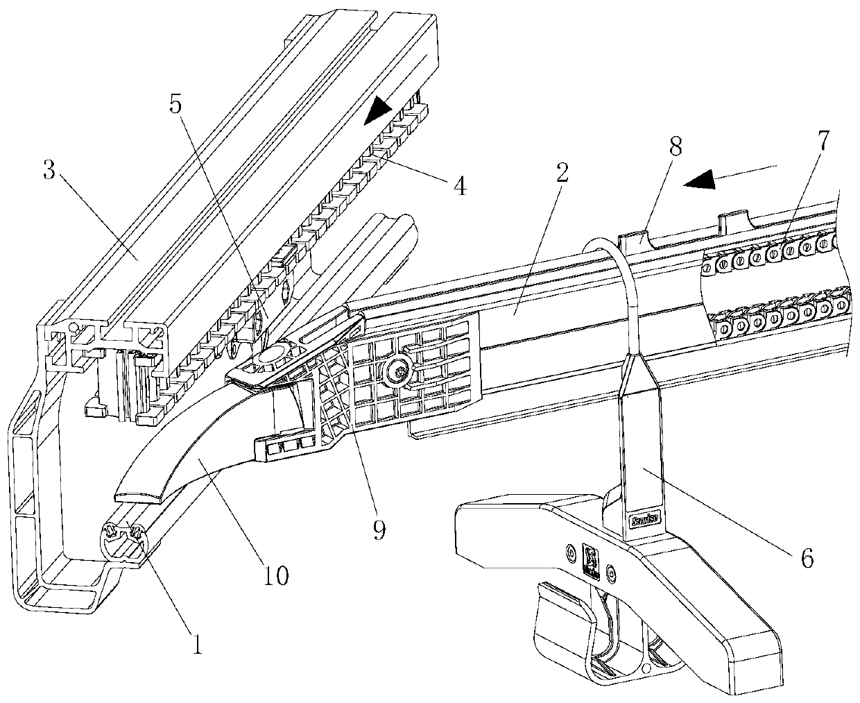
[0021] Such as Figure 1-5 As shown, the conveying line has a main rail 1 and a branch rail 2, and the branch rail 2 is arranged on one side of the main rail. A vehicle driving line is provided above the main rail 1, including a driving rail 3, a rack assembly 4 installed on the driving rail 3, and a tow hook 5 installed below the rack assembly 4. The carrier 6 can be hung on the main rail 1 and pushed forward by the tow hook 5 . There is a chain drive assembly inside the branch rail 2, the chain drive assembly includes a chain 7, the chain 7 is driven by the sprockets at both ends of the branch rail, a number of push rods 8 are installed on the chain 7, and the push rods 8 run in the middle groove of the branch rail , and expose the surface of the rail 2, so that the carrier 6 hanging on the rail 2 can be pushed forward. It is foreseeable that the branch rail 2 can also adopt the same structure as the main rail 1 .

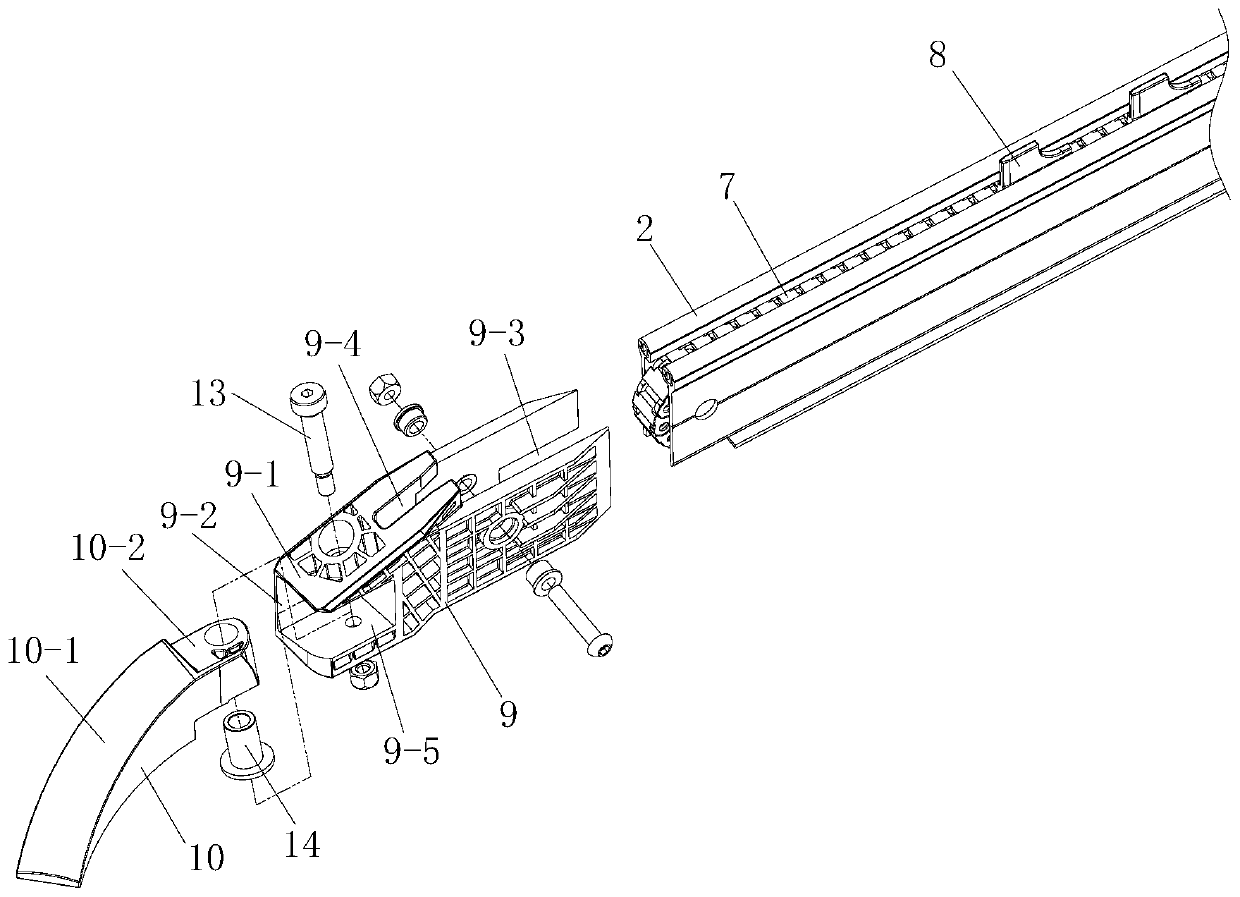
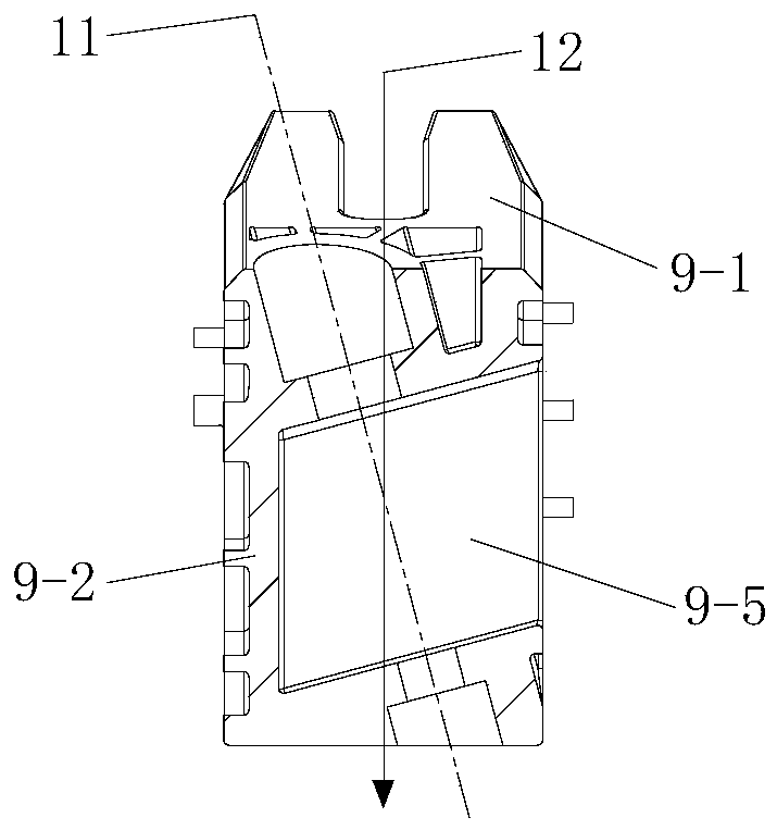
[0022] The merging mechanism includes a fixed seat 9 and...


PUM


Abstract

The invention provides a conveyor line flow-combination mechanism which is used for connecting rails. The rails comprise a main rail and a branch rail; the conveyor line flow-combination mechanism isarranged on the branch rail and comprises a fixed seat and a swinging head; one end of the fixed seat is connected with the branch rail; the swinging head can be rotatably arranged at the other end ofthe fixed seat; the free end of the swinging head is located above the main rail; the swinging head can be pushed away from the upper part of the main rail through an acting force along the main railrunning direction; the conveyor line flow-combination mechanism further comprises a swinging head resetting mechanism; and after the acting force along the main rail running direction is disappeared,the swinging head is reset under the action of the swinging head resetting mechanism. The conveyor line flow-combination mechanism provided by the invention not only can be applied to a roller clothes hanger hanging assembly line but also can be applied to a pothook carrier assembly line.

Description

technical field [0001] The invention relates to the technical field of hanging conveying lines, and mainly relates to a confluence mechanism. Background technique [0002] Chinese invention application 2017103679450 discloses "a confluence mechanism" for connecting rails. The rails include a first branch rail, a second branch rail, and a confluence rail. The outlet end of the first branch rail is connected to the inlet end of the confluence rail. The branch rail is disconnected from the confluence rail, and the first branch rail, the second branch rail, and the confluence rail are all equipped with roller hanger convex rails, and the first branch rail and the roller clothes hanger convex rail on the confluence rail are connected end to end to form a continuous convex rail The confluence mechanism includes a fixed seat and a swing head, the fixed seat is installed on the outlet end of the second branch rail, one end of the swing head is rotatably installed on the fixed seat, ...

Claims


Application Information

Patent Timeline
Patent Type & Authority Applications(China)
IPC IPC(8): B65G17/20B65G47/68
Inventor 孙迪韩博学袁峰
Owner 沈阳瑞晟智能装备有限公司
Why Eureka
Try Eureka